Colorado-based Martin/Martin, Inc. is a consulting engineering firm providing civil and structural engineering and surveying services to clients throughout the United States and around the world. Within Martin/Martin, the Construction Engineering Services (M/M CES) group provides a variety of specialty engineering services to the firm’s contractor partners and projects, including the development of rebar shop and fabrication drawings. Both Martin/Martin and the M/M CES team use Autodesk Revit software for engineering design and documentation.
One of the firm’s most recent projects was the expansion of a semiconductor plant for Broadcom, located in Fort Collins, Colorado. During the past several years, the company invested approximately $1 billion in new construction on this 70-acre campus which included the addition and expansion of a new reinforced concrete manufacturing facility in 2014 and 2015. On both of these jobs, the extended project team—including Martin/Martin, M/M CES, and the general contractor JE Dunn Construction—used Building Information Modeling (BIM) processes and Revit software.
The major challenge on these projects was aggressive construction schedules. JE Dunn was engaged early in the projects and was actively involved in the design process to enhance constructability and keep the projects on track and within budget. “Close collaboration during the design phase of these projects resulted in higher quality buildings for the client,” says Shane Ewing, a principal at Martin/Martin and the manager of the M/M CES team. From previous experience with Martin/Martin and the M/M CES team, JE Dunn knew that one big opportunity for time savings during construction was concrete rebar detailing.
Revit for rebar detailing helps save time and money
“Rebar detailing typically begins several weeks after a contractor is awarded a project and is performed in isolation from the design team by a detailer working solely from 2D design drawings,” explains Ewing. “This situation forces a late start and often results in poor coordination with other trades, which further jeopardizes construction schedules.”
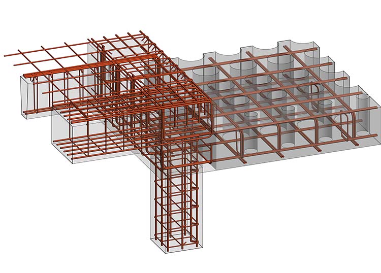
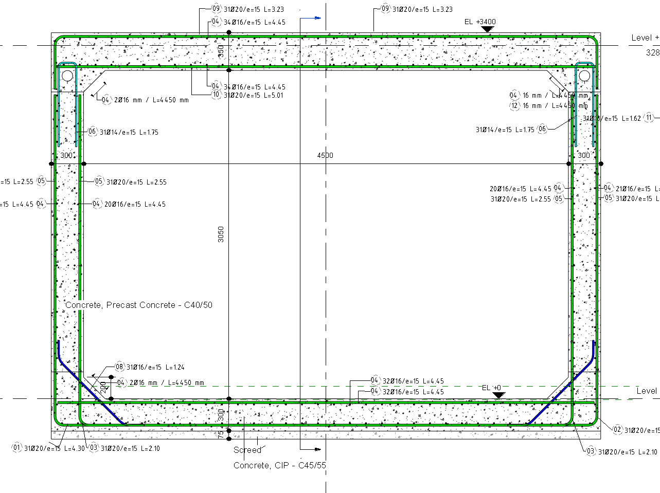
To help counter this situation, M/M CES used Revit to develop reinforcing steel fabrication drawings. “Instead of waiting until the construction documentation was completed, we started detailing during the design phase based on the structural designer’s Revit model,” says Grant Doherty, a BIM specialist at Martin/Martin. “By working closely with the design team, we could coordinate the rebar with the structure and other trades to improve constructability and quality.”
“Developing the steel reinforcement directly in the Revit structural design model, weeks before construction documents were available to anyone else, helped to provide significant schedule, quality, and cost benefits for the client—benefits that just couldn’t be matched using other detailing software.”
―Shane Ewing, Principal, Manager of Construction Engineering Services, Martin/Martin
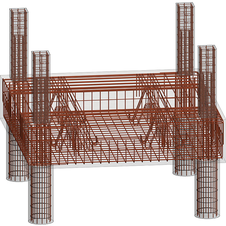
In addition, when the firm issued final construction documentation to JE Dunn, it also issued approved fabrication documentation. “Working with the design team and using a common Revit model, we began and completed our shop drawings earlier than a traditional ‘third party’ detailer would have,” says Ewing. For example, on a traditional project, rebar drawings are usually delivered five to eight weeks after the release of the construction documents. But on the first Broadcom building, the M/M CES team delivered an approved drilled pier and foundation rebar package in less than two weeks after the release of the construction documents. “With support from BIM processes and Revit for rebar detailing, we were able to save three to six weeks on this project,” says Ewing.
Model-based detailing and fabrication ready
When working together on a project, the M/M CES team and Martin/Martin structural designers use the same Revit structural model, which often includes the architectural model as well as models from other building disciplines. On the Broadcom project, this enabled a level of project coordination what would not have been possible with traditional 2D detailing.
Beyond project coordination, using Revit for detailing also helped improve the overall quality of the firm’s rebar product. “Other detailing programs tend to ignore the experience and knowledge of the detailers by relying on software algorithms to add steel reinforcements,” says Doherty. “But more often than not, those algorithms don’t result in the best or most economical solution.” The Revit software and its 3D modeling environment helped the M/M CES team draw on their own detailing knowledge, as well as the experience of the Martin/Martin designers, to deliver the project’s fabrication package more efficiently and cost-effectively.
“Model-based detailing helps us work through complex design issues by using 3D views and live schedules to check the rebar,” says Doherty. “And because we work in tandem with the design team, we can see design changes as they happen and react more quickly. In fact, we can often release detailing revisions to the fabricator before the design team formally issues their changes.”
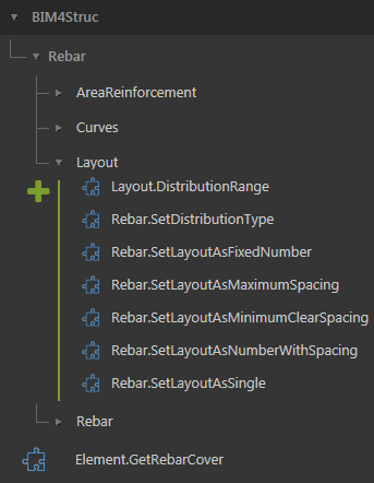
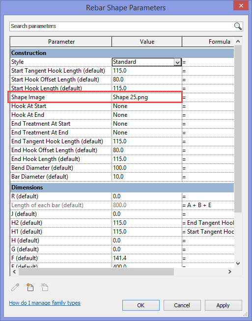
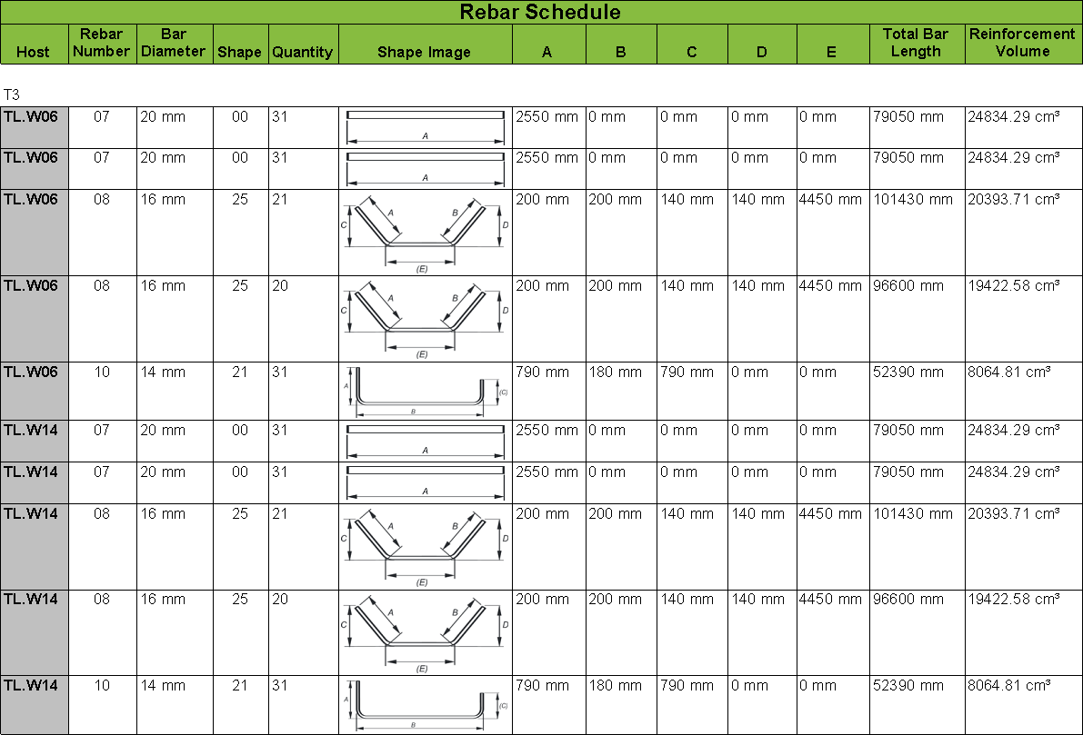
For its rebar detailing, M/M CES has created “fabrication ready” customized Revit rebar families. The rebar sizes, lengths, and bends in these families were all developed using industry standards and can be used by any North American fabricator.
Accelerate project schedules
With Revit, every drawing sheet, 2D and 3D view, and schedule is a direct presentation of the underlying model. The parametric engine at the heart of the Revit software enables the automatic synchronization of the model and all the associated drawings, views, and so on. “The automatic change management inherent in the Revit software helped us to quickly incorporate design changes,” says Doherty. “We could change the rebar in the Revit model, and that change automatically appeared in our fabrication drawings. There was no need for us to spend time on manual updating or quality control.”
Control costs
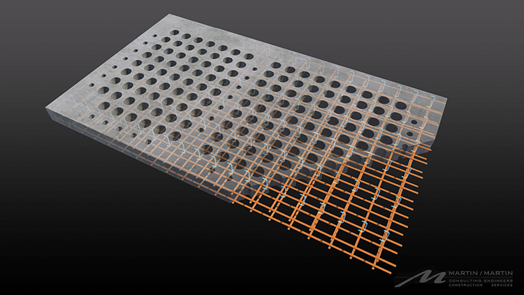
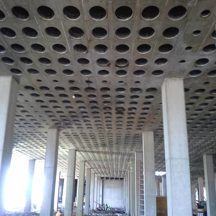
The Revit software and its 3D modeling environment helped Martin/Martin minimize project costs by enabling the M/M CES team to draw on their own detailing experience to more effectively layout the rebar and locate bar splices. For example, the first Broadcom project included a large concrete ‘waffle’ slab that needed a lot of reinforcement. “Working with the design team, the contractor, and the rebar placer, we were able to quickly try out different options in the Revit model and estimate tonnages to optimize the layout and splice locations,” says Doherty. As a result, the team was able to cut the number of bar splices in half, and reduce the tonnage by 8 tons and the number of bars handled by more than 2,000—helping Broadcom save an estimated 5 percent in material and labor costs.
Reduce field issues
“Model-based project coordination combined with the completeness and quality of the fabrication drawings resulted in less field issues,” reports Ewing. In addition, the M/M CES team shared its Revit-based rebar model with the contractor and rebar installer to provide even more rebar information in a more accessible format. For example, the 3D rebar model enabled JE Dunn to coordinate the rebar with other trades and also use it as a starting point for its own concrete lift drawings.
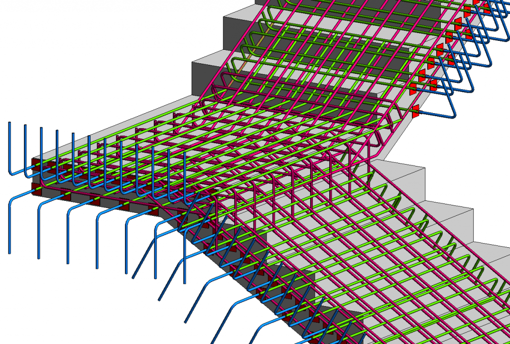
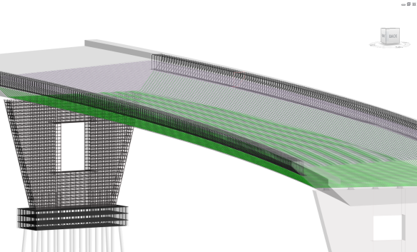
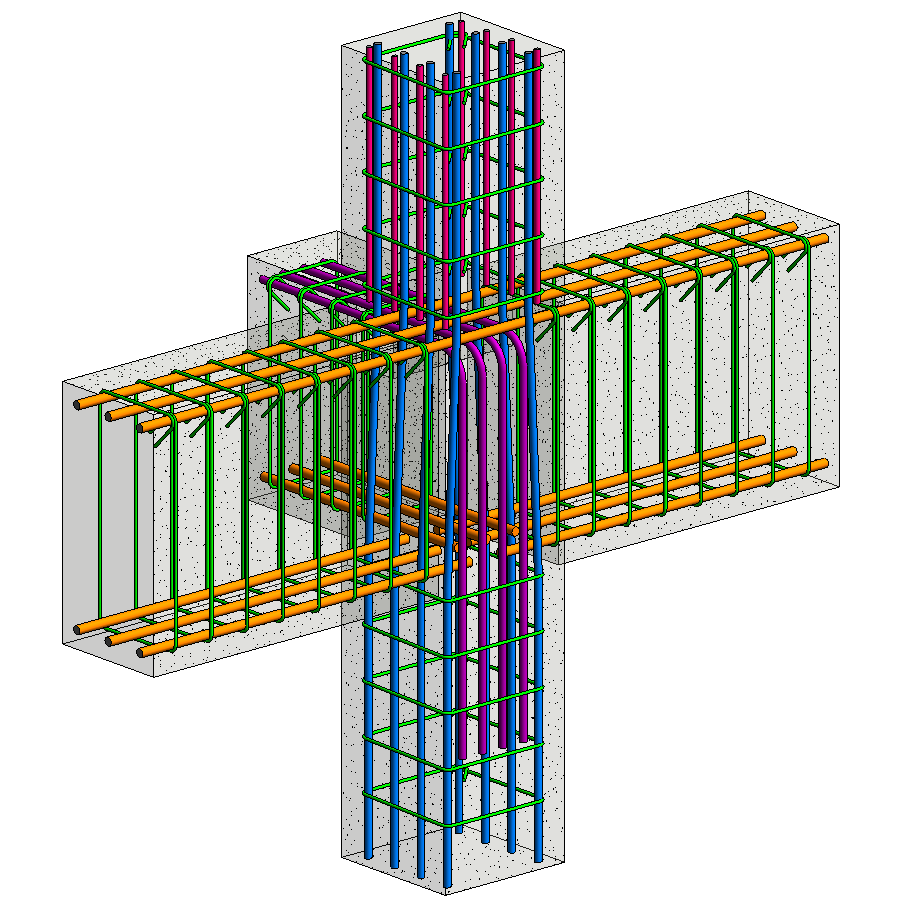
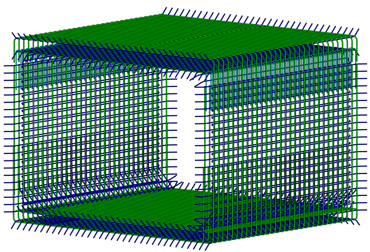
The Revit rebar model was also used to easily create live section cuts through the rebar model and produce 3D perspective views of complex areas for visual clarification during construction. M/M CES even color-coded the rebar model to show the sequence of rebar installation. The ability to view the rebar model from any angle—either on a monitor in a trailer at the jobsite or even tablets in the field—helped the construction team visualize and better understand the rebar layout.
The results
“Using BIM processes and Revit software for rebar detailing helped us meet all of the project schedules,” says Doherty. “We delivered coordinated shop drawings earlier than would normally have been possible. And by relying on our own detailing experience, we delivered a higher-quality fabrication package that provided a better understanding of contract documents and helped minimize project costs.”
“Developing the steel reinforcement directly in the Revit structural design model, weeks before construction documents were available to anyone else, helped provide significant schedule, quality, and cost benefits for the client—benefits that just couldn’t be matched using other detailing software,” says Ewing.
Learn More
To learn more about Autodesk Revit’s features for structural engineers, including rebar detailing, visit Autodesk.com/products/revit-family. Or read these past blog posts on Revit’s features for rebar detailing:
- BIM for reinforced concrete: it’s in the details
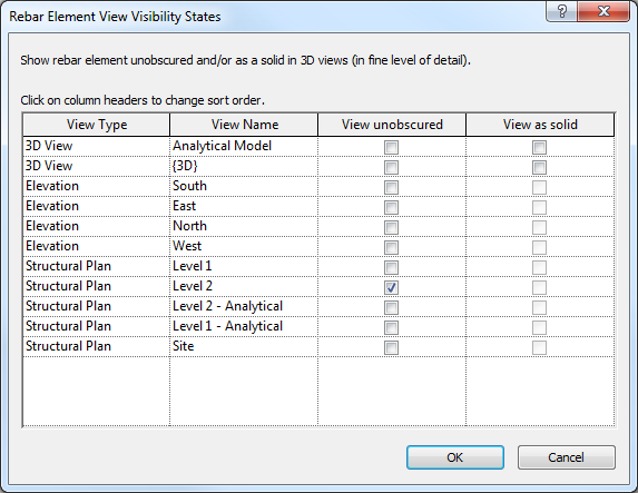
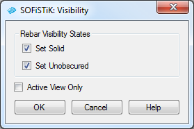
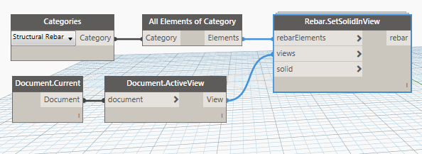
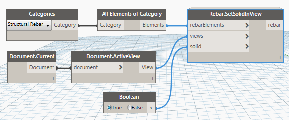
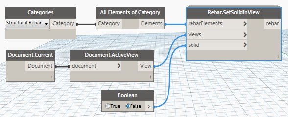
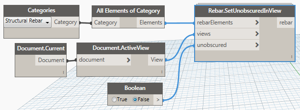
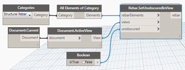
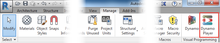
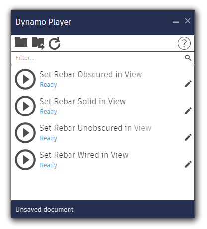
- How to deal with rebar visibility in Revit
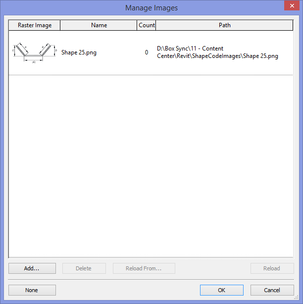
- Rebar shape images in Revit
The post Attention to detail – Revit for rebar detailing appeared first on BIM and Beam.
from my Autodesk source Bim & Beam: BIM and Beam at http://blogs.autodesk.com/bim-and-beam/2016/12/26/revit-for-rebar-detailing/
via IFTTT
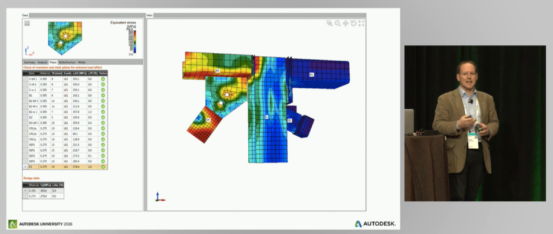
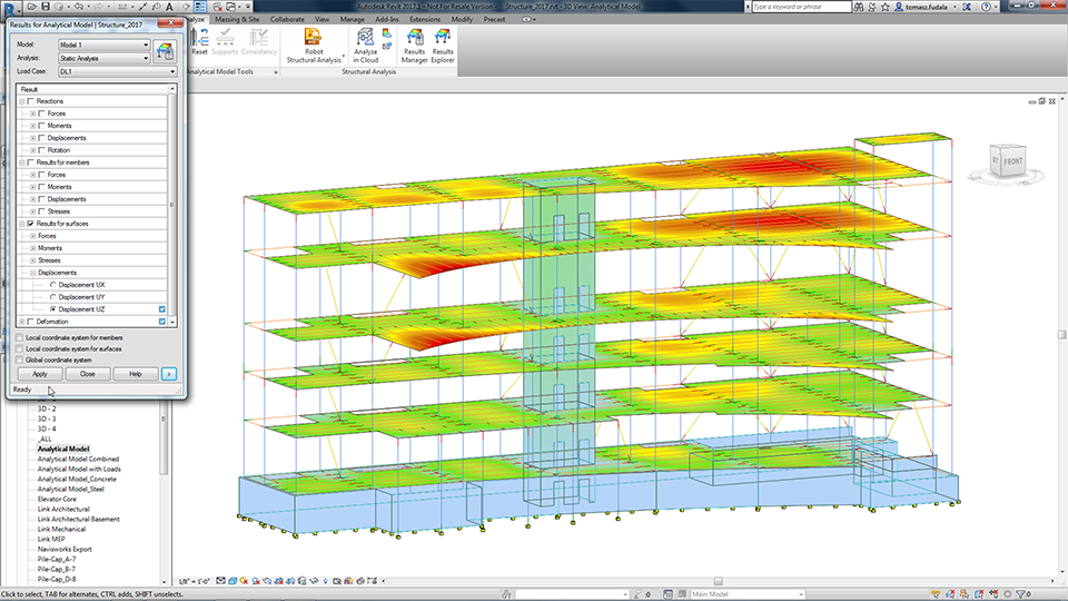
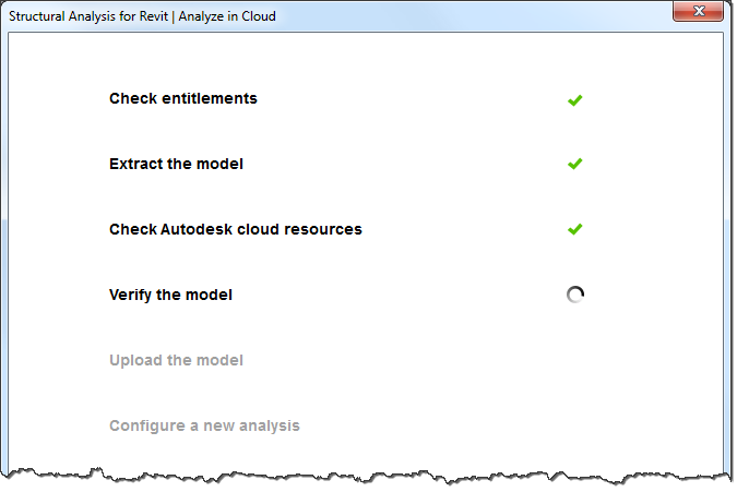 Verification of the model before it is uploaded checks if it is correct from the viewpoint of structural analysis. This verification ensures that the model being analyzed is correct and the analysis results are reliable. It also prevents uploading models with errors to the website.
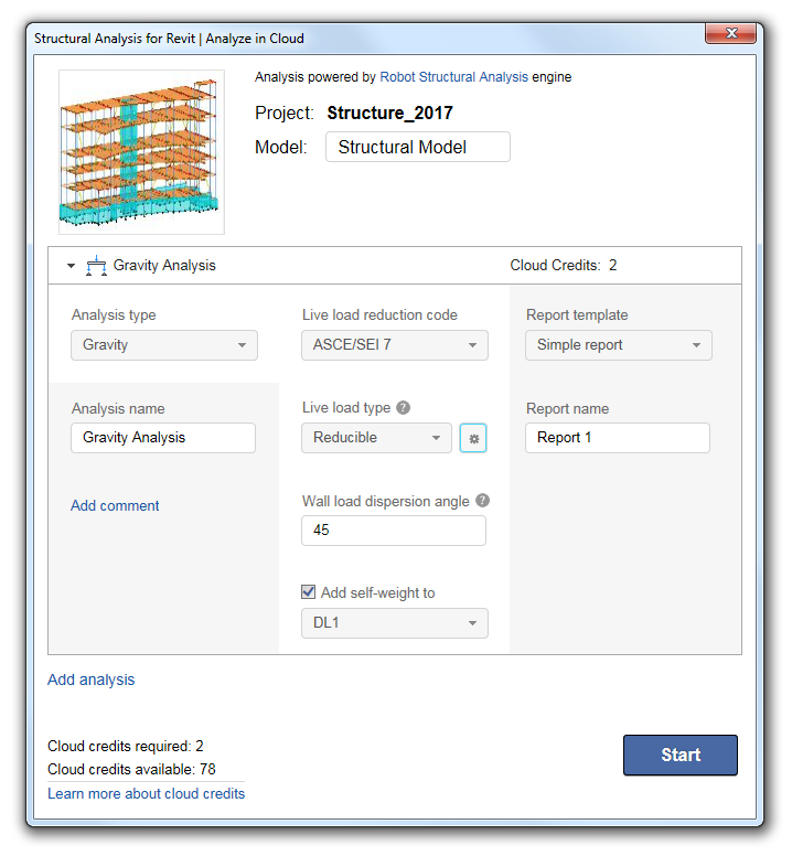
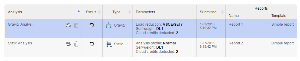
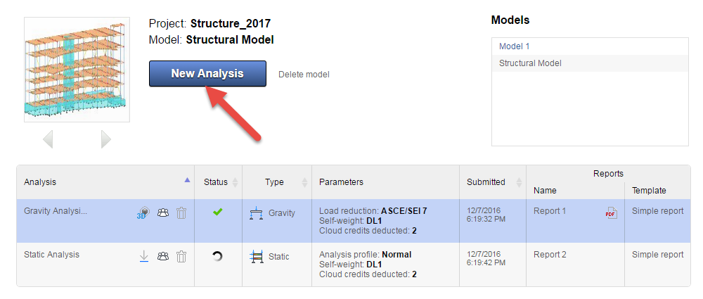
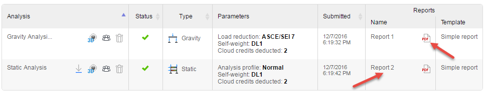
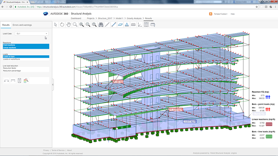
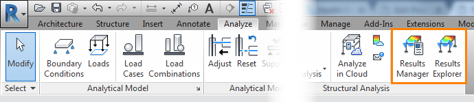
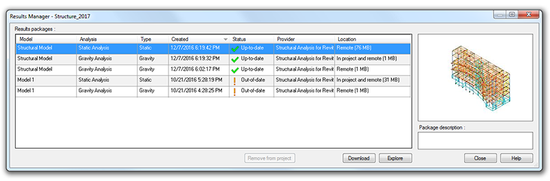
 Results Manager dialog box shows the list of available results packages, as well as their status and location. The results of the analysis you performed can be stored in several ways: