Wednesday 28 June 2017

Updated Standard Structural Steel Families for Revit

New content for the Southern Hemisphere and much more

As an ongoing process, Autodesk is updating Revit content every year to match the local standards from all over the world.

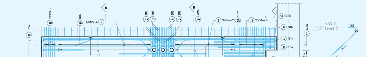
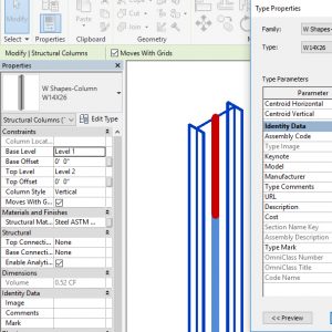
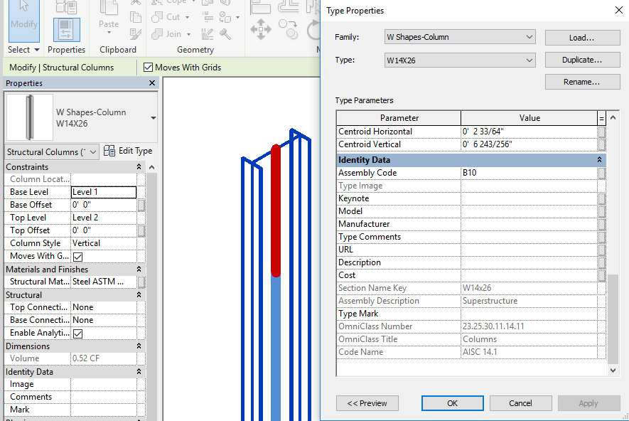
With the 2017 release, Revit obtained a new structural detailing tool, Steel Connections for Revit,” an extension that can be installed from the Autodesk Desktop-App to model typical steel connections on framing elements. At the same time, new framing and column families were shipped with Revit, supporting the connection code check with exact and complete information on section geometry and analysis parameters.

While the first content release was focused on the United States, Canada and four European countries, we continued to enhance structural content for other regions all over the world – one of the most common requirements suggested during conversations with our international sales partners. A second step was made with the 2017.2 version in autumn last year, when Japanese and Chinese framing section families were delivered. Most recently, the standard structural steel families were extended for Australia, New Zealand, South-Africa, India and several more European regions like Scandinavia in the spring of this year. All the mentioned new families are delivered with the Revit 2018 installation out of the box. And there’s more to come! Right now, the team is again updating the content for even more regions.

U.S. Imperial structural columns

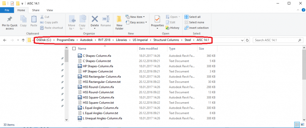
File location of U.S. Imperial structural columns as an example

German structural column

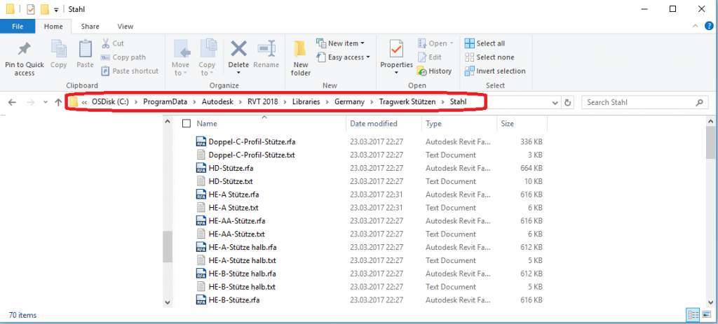
File location of German structural columns as an example.

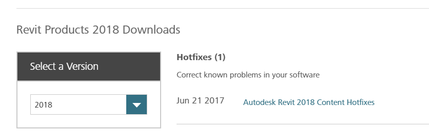
A complete list with the available content and the file location can be found here. Keep a look out for new content by checking the Revit Product Downloads page from time to time for new updated content available for your region. For example, you can find there the new structural framing families mentioned above for Revit 2017 as well as a fix for some European framing families for Revit 2018 that enable the smooth model synchronization with Advance Steel.

Revit 2018 Content Hotfixes

What do you think about Revit’s out of the box content? How often are you using Autodesk structural framing and column families in your projects? Are you missing section sizes for your region or special parameters for your content? Let us know!

The post Updated Standard Structural Steel Families for Revit appeared first on BIM and Beam.


from my Autodesk source Bim & Beam: BIM and Beam at http://blogs.autodesk.com/bim-and-beam/2017/06/28/updated-structural-steel-families-for-revit/
via IFTTT

Monday 26 June 2017

Arup uses Dynamo to advance the pace of collaboration on the proposed National Football Stadium in Sydney

Full Stadium Rendering

The structural engineers at Arup in Australia take on some of the country’s most challenging projects. So it’s no surprise that they paired with the architects at Populous to design the structure for the proposed, 60,000‑seat National Football Stadium in Sydney. That’s because the architects’ initial designs featured curving organic forms and plans for Australia’s first cable net roof for a major stadium. The Arup team was tasked with bringing innovative and cost-effective structural ideas to the project’s concept phase—and they had just 12 weeks to collaborate with the architects and deliver.

The Arup team realized that they needed a way to both quickly explore the best structural options for the project and to increase documentation efficiency. A computational design tool was the ideal solution. They chose to work with Autodesk Revit software, their core documentation application, and Dynamo software. Autodesk Revit with Dynamo powered the project forward, letting the team advance the concept twice as quickly as compared to traditional methods. And now it’s transforming the way that Arup delivers other projects.

“We used Dynamo to rationalize and apply a logic to a complex structure. The powerful part of Dynamo is how it let us develop and improve on concepts quickly. Because of the pace it brought to our workflow, we did 12 iterations instead of 3 or 4.”
— XAVIER NUTTALL Structural Engineer, Arup

12 concepts in 12 weeks

With only 12 weeks for the documentation of the concept design, Arup needed to get started right away with Dynamo—there was no time for a steep learning curve. The documentation lead on the project had little scripting experience in Dynamo, but she was able to quickly create master scripts thanks to the intuitive nature of the process. These scripts let the engineers explore and document multiple structural options that suited the ever-evolving architectural forms. The scripts automated much of the tedious work behind efficiently modeling and documenting the geometrically complex stadium. During the early stages of concept design, Dynamo let the Arup and Populous teams quickly and efficiently collaborate, resulting in an iconic, well-coordinated, and optimized stadium design. This was particularly advantageous in helping to de-risk the complexity of the design while also informing costing and feasibility.

Interoperability between Dynamo software, Revit software, and Arup’s preferred structural analysis tool helped the team to rapidly create design iterations. They shared their ideas with the architects and collaborated in a 3D Revit environment to enhance the overall design. In all, the team developed 12 concepts, each of which advanced and improved on the preceding one. Absent Dynamo, the team estimates that they would have only had time to develop and document 4 structural concepts. Dynamo automated many of the tedious tasks in the documentation process, saving more than 5 weeks on documentation, which allowed the team to devote more effort than expected to coordinating and optimizing their designs.

The bold, curving shapes featured in the design for the proposed National Football Stadium in Sydney, Australia required innovative structural support. Images courtesy of Populous.


More design, fewer boring tasks

Success on the stadium project inspired Arup to apply the conceptual design and automation ability of Dynamo to more projects. The firm began teaching its documentation specialists throughout Australia how to create their own scripts. Arup also started a script library to share timesaving scripts, allowing the Arup documentation team to spend less time on tedious tasks, and more time on design optimization for their everyday projects.

“Tedious documentation tasks that would have taken 4 hours only took 10 minutes using Dynamo. The savings we realized gave us more time to finesse better design solutions.”

— SHAWNEE FINLAYSON, Structural Technician, Arup

ABOUT ARUP

Founded in 1946, Arup is one of world’s largest engineering firms, with as many as 10,000 projects in progress at any time. The firm came to Australia in 1963 to work on the landmark Sydney Opera House. Today, Arup operates 7 offices in Australia. Recent projects include the new Perth Stadium, Adelaide Oval Redevelopment, Barangaroo, and 8 Chifley, which is one of Australia’s greenest buildings.

ABOUT POPULOUS

Populous designs places where people love to be together, like Yankee Stadium and the London Olympic Stadium. A global architecture firm, Populous has designed more than 2,000 projects worth $40 billion across emerging and established markets. The firm has 17 offices on 4 continents.


The post Arup uses Dynamo to advance the pace of collaboration on the proposed National Football Stadium in Sydney appeared first on BIM and Beam.


from my Autodesk source Bim & Beam: BIM and Beam at http://blogs.autodesk.com/bim-and-beam/2017/06/26/arup-national-football-stadium-in-sydney/
via IFTTT

Wednesday 14 June 2017

David Weaver from Mold-Tek shares what steel fabricators can learn from green chili

David Weaver Mold-Tek

Autodesk is excited to welcome David Weaver, Vice President at Mold-Tek Technologies Ltd as a guest contributor to BIM and Beam. David is an evangelist and thought leader for the steel industry, and shares a unique insight on how project teams collaborate.

(or why fabricators should be happy if their detailer is asking a lot of questions)

Growing up and living in Colorado, a frequent meal for me is to take whatever food is around and smother it in a good green chili sauce. Top it with sour cream and guacamole, and serve it with a side of tortillas. There are even thriving local chain restaurants whose entire business model is to take the cheapest ingredients possible and smoother them in top notch green chili.

My mother in law has a different taste in food. She grew up in Massachusetts and spent most of her adult life in Northeast Virginia, Fairfax. I still remember the look of … concern in her face the first time she saw me do this. She is a great cook, and I have always enjoyed eating her food, but let’s just say that my ingredients and techniques are not within her repertoire.

What can a fabricator learn from this? Simple. That standards and techniques can be regional. Just because a shop or erector has always been doing something a certain way, doesn’t mean that it is an industry standard. Take for example the angle or bent plate attached to a beam top flange to form an edge of slab detail. In Colorado, the typical approach is for it to be fully field attached. The field even cuts the pieces to length and performs any other cuts to get it around columns. Alternatively, there is a fabricator in the New England area that will shop attach it, but only with bolts in long slots, so that the field can perform adjustments then weld into position. I’ve also seen projects in Las Vegas where this material is shop attached and welded with no field work.

A typical edge of slab detail (Courtesy of Mold-Tek Technologies Ltd.)

My point is, things that fabricators think are industry standards might be unique to their region, or even only unique to their company.

It used to be that detailers worked regionally. It was too cumbersome and caused too much of a delay to ship physical drawings too great of a distance. But today’s technology allows electronic drawing files to be sent across the world in the matter of seconds. It often takes longer to type the email notifying the fabricator that drawings are posted to a file sharing site, then it does to actually post the drawings. This allows detailers to work across all regions of the US and even the world. Meaning they might not be familiar with the exact approach that a fabricator wants to use for a specific detail. This is especially true for the first time a detailer works with a fabricator.

A detailer with little experience will not know when to ask for the fabricator or erector’s preference. They may just apply the same approach that they used on their last project, even though that last project was for a different fabricator who has different preferences. Experienced detailers know when to ask about preferences. Unfortunately, this results in probably the biggest complaint I hear from fabricators, “The detailer is asking too many questions!” (typically in much more colorful language that I am using here).

Questions are exactly what you want from your detailer. When a detailer is flooding you with basic questions, don’t assume they are delaying the project, or are inexperienced. In reality, they might have just the right amount of experience to know that the question needs to be asked.

Related Articles

How to forge a detailer-fabricator relationship as strong as steel

The post David Weaver from Mold-Tek shares what steel fabricators can learn from green chili appeared first on BIM and Beam.


from my Autodesk source Bim & Beam: BIM and Beam at http://blogs.autodesk.com/bim-and-beam/2017/06/14/david-weaver-mold-tek-guest-post/
via IFTTT

Thursday 8 June 2017

Multi-Rebar Annotation in Revit

A reinforcement drawing shows the positions of all reinforcing elements in a particular structure or a structural element. There are numerous ways of drafting concrete shop drawings, and drafting styles vary between countries or even between design companies.

Rebar in Revit comes with properties that can be read by predefined tags (families) created specifically to read the rebar settings. It’s possible to let Revit tag these items automatically, or you can manually tag the items.

Multi-rebar annotations significantly improve rebar detailing workflow. A multi-rebar annotation allows you to tag multiple rebar and rebar sets with a single annotation.

You can use these multi-rebar annotations to tag each bar in a rebar set with a detailed annotation for fabrication and construction.  Thanks to this functionality, drawing creation becomes quite smooth and productivity increases incomparably.

If you want to use this functionality in Revit you need to go on the Annotate tab -> Tag panel and under Multi-Rebar you can find the following two tools:

  • Aligned Multi-Rebar Annotation
  • Linear Multi-Rebar Annotation

Once you run one of them then you simply select rebar sets or individual rebars to have them annotated by one single annotation.  You can also modify multi-rebar annotations like other tags.

A Multi-rebar annotation family is a Revit system family. In the Type Properties you can find a tag family and a dimension style that can be easy configured and adjusted.

For more posts on Revit’s rebar features, check out these past articles on BIM and Beam:

The post Multi-Rebar Annotation in Revit appeared first on BIM and Beam.


from my Autodesk source Bim & Beam: BIM and Beam at http://blogs.autodesk.com/bim-and-beam/2017/06/08/multi-rebar-annotation-revit/
via IFTTT

Friday 2 June 2017

6 IMPORTANT ENGINEERING PROPERTIES OF MORTAR

Properties of Mortar Properties of mortar which are sought for use in masonry are: workability, water retentivity, rate of stiffening, strength, resistance to rain penetration and durability. These properties have been discussed below explaining their effect on masonry. Choice of masonry mortar is governed by several considerations such as Type of masonry unit and its […]

The post 6 IMPORTANT ENGINEERING PROPERTIES OF MORTAR appeared first on CivilBlog.Org.


from CivilBlog.Org http://civilblog.org/2017/06/02/6-important-engineering-properties-mortar/
via Our favorite Civil Engineering Blog

Thursday 1 June 2017

Sofistik Reinforcement Detailing 2018 is Available

SOFiSTiK Reinforcement Detailing significantly accelerates the creation of 2D reinforcement sheets out of 3D models in Autodesk® Revit®. The product consists of software and a set of families, which can easily be modified to meet local or company standards. Creation of bar lists, bending schedules and cut lists for wire meshes is included as well.

Functionalities at a glance:

  • Customizable Content Packs in order to reach individual standards.
  • Operational Modes: Marks per project, – sheet or – host.
  • Set Marks according to additional criteria’s like running length, not bent, couplers etc.
  • Customizable reinforcement schedules and cut lists for fabric sheets.
  • Group bars to a specific SOFiSTiK Rebar Container according its layout.
  • Copy Reinforcement with all annotations, details, dimensions and related views.
  • SOFiSTiK Multiplier for the quantity of Rebar Sets and Fabric Sheets.
  • Stagger segment lengths of SOFiSTiK Variable Rebar Set.
  • Split Rebar Sets or – Shapes according to set stock length and splice or using dividing lines.
  • Detailing tools to indicate the rebar layout, – bar ends, – layers, etc.
  • Rebar or Fabric Shape Details to represent the partial rebar set or the entire mark.
  • Shape Code detection according to various national standards.
  • Reinforcement Layer functionality in floors, walls and foundation slabs.
  • Browse through the marks of rebars and fabric sheets.
  • Distribute reinforcement in elements with complex shapes and faces.
  • Creation of bent fabrics rows according to a given length.
  • Revisions for reinforcement sheets and corresponding schedules.
  • Freeze/Unfreeze of reinforcement geometry and properties.
  • Export BVBS reinforcement data as *.abs file for bending machine.

You can download a 30-day trial of these tools from the Autodesk App Store.

The post Sofistik Reinforcement Detailing 2018 is Available appeared first on BIM and Beam.


from my Autodesk source Bim & Beam: BIM and Beam at http://blogs.autodesk.com/bim-and-beam/2017/06/01/sofistik-reinforcement-detailing-2018-available/
via IFTTT