Saturday 30 December 2017

Design procedures for a Building Foundation (Step by Step)

Design Procedures for a Building Foundation (Step by Step) Good design must not only be safe but must aim to save construction costs, time and materials. The following procedures should help to achieve this and an ‘educated’ client will recognize the importance of funding this work with a realistic fee. 1. Type of Load On […]

The post Design procedures for a Building Foundation (Step by Step) appeared first on CivilBlog.Org.


from CivilBlog.Org http://civilblog.org/2017/12/30/design-procedures-building-foundation-step-step/
via Our favorite Civil Engineering Blog

Monday 4 December 2017

Segmentation of Precast Walls in Revit

In this post of the Structural Precast series I would like to touch upon the topic of segmentation of precast walls.

Segmentation of precast walls can be done automatically or manually. Before we run the automatic segmentation we should check and adjust the Configuration Settings.

The Configuration settings can be imported or exported via XML files to easily share the rules across several users, working on the same or different projects.

The Configuration settings can be imported or exported via XML files

On the Part Tab we set up Lifters, Bracing Inserts and Connections. Here we decide what types of elements will be used and their positions within precast assemblies.

Segmentation of Precast Walls

All the connections and built-in parts are Revit families and can be customized according to the project’s requirements.

On the Segmentation Tab we define rules for splitting based on fabrication, transportation or other functional requirements.

Segmentation of Precast Walls

To execute a segmentation of walls we need to select all the walls and press the Split command. During this command, the precast wall assemblies are created. Lifters, bushings and connection are created according to the rules from the Configuration settings.

Split

Just after the wall segmentation we can see both the original elements and parts that have just been created.

We can display parts only to better review the outcome of the Split.

Switching between different LODs (Level of Development) is pretty easy and fast so we can review the original elements at any time.

As an outcome of the Split command we get wall parts, lifters, bushings and connections grouped automatically into a precast assembly.


Watch video:

When a custom segmentation is performed, it often does not allow for clear mathematical rules and we cannot apply rules specified in the Configuration. At this point we need to perform the manual segmentation of the original walls.

The manual segmentation is performed starting directly from the original, unsegmented element.

First, we need to convert a wall into Revit Parts.

Next, we define a division line or lines. Drawing such division line(s) we can very precisely determine where a segmentation should occur.

Once manual segmentation is complete, the “Split” command can be used to convert the parts into precast assemblies.

Now on this floor we have a mixture of original walls and parts we just created manually.

IMPORTANT TO NOTE: If the original wall is selected, instead of the manually created parts, the manual segmentation is overridden and the wall is segmented according to the Configuration settings. That’s why it’s important to make sure the original element is not selected but only parts.

If one part is still larger/heavier/etc. than the specifications indicated in Configuration Settings, it will be further divided, respecting those rules.

Let’s see the outcome of the segmentation in this case.

Another way we can control the segmentation of elements is by a manual adjustment of parts after the segmentation.

In this case we select a part and edit a position of a division line – this can be done very precisely too. Once the part is updated, the entire assembly and connections, lifters, and bushings are updated as well.

We can also manually adjust a position or a type of individual elements within an assembly. In this case I am changing a position of one of the bushings.

In the similar way, we can update lifters and connections within a precast assembly.

Watch video:

For more posts on structural precast in Revit, check out these past articles on BIM and Beam:

@tomekf

The post Segmentation of Precast Walls in Revit appeared first on BIM and Beam.


from my Autodesk source Bim & Beam: BIM and Beam at http://blogs.autodesk.com/bim-and-beam/2017/12/04/segmentation-of-precast-walls-in-revit/
via IFTTT

Friday 3 November 2017

10 PRACTICAL PROBLEMS TO THINK BEFORE DESIGNING A FOUNDATION

PRACTICAL PROBLEMS TO KEEP IN MIND BEFORE FOUNDATION DESIGN There are, in foundation design, a number of practical construction problems and costs to be considered. The chief ones are: The foundations should be kept as shallow as possible, commensurate with climatic effects on, and strength of, the surface soil; particularly in waterlogged ground. Excavation in […]

The post 10 PRACTICAL PROBLEMS TO THINK BEFORE DESIGNING A FOUNDATION appeared first on CivilBlog.Org.


from CivilBlog.Org http://civilblog.org/2017/11/04/10-practical-problems-think-designing-foundation/
via Our favorite Civil Engineering Blog

Thursday 26 October 2017

SOFiSTiK | 2018 – presentation day in London

The “SOFiSTiK | 2018 – presentation days” are aimed at entrepreneurs, interested structural engineers, and experienced SOFiSTiK users who want to learn more about the latest developments in construction planning.

SOFiSTiK’s development goals for the version 2018 were to optimize usability and performance in combination with a totally redesigned workflow for BIM analysis and design.

In their presentation day, they will present the new features and workflows of SOFiSTiK | 2018 using application examples focusing on FEA and BIM.

Read more…

The post SOFiSTiK | 2018 – presentation day in London appeared first on BIM and Beam.


from my Autodesk source Bim & Beam: BIM and Beam at http://blogs.autodesk.com/bim-and-beam/2017/10/26/sofistik-2018-presentation-day-london/
via IFTTT

Wednesday 18 October 2017

Top 10 Features in Advance Steel 2018

Advance Steel 2018 Badge 790px

The new release of Advance Steel 2018 has been out for a few months now. Here is a highlight of the top 10 features in case you haven’t had the chance to get familiar with them yet.

Advance Steel 2018 Badge 790px


1 – One Advance Steel installation

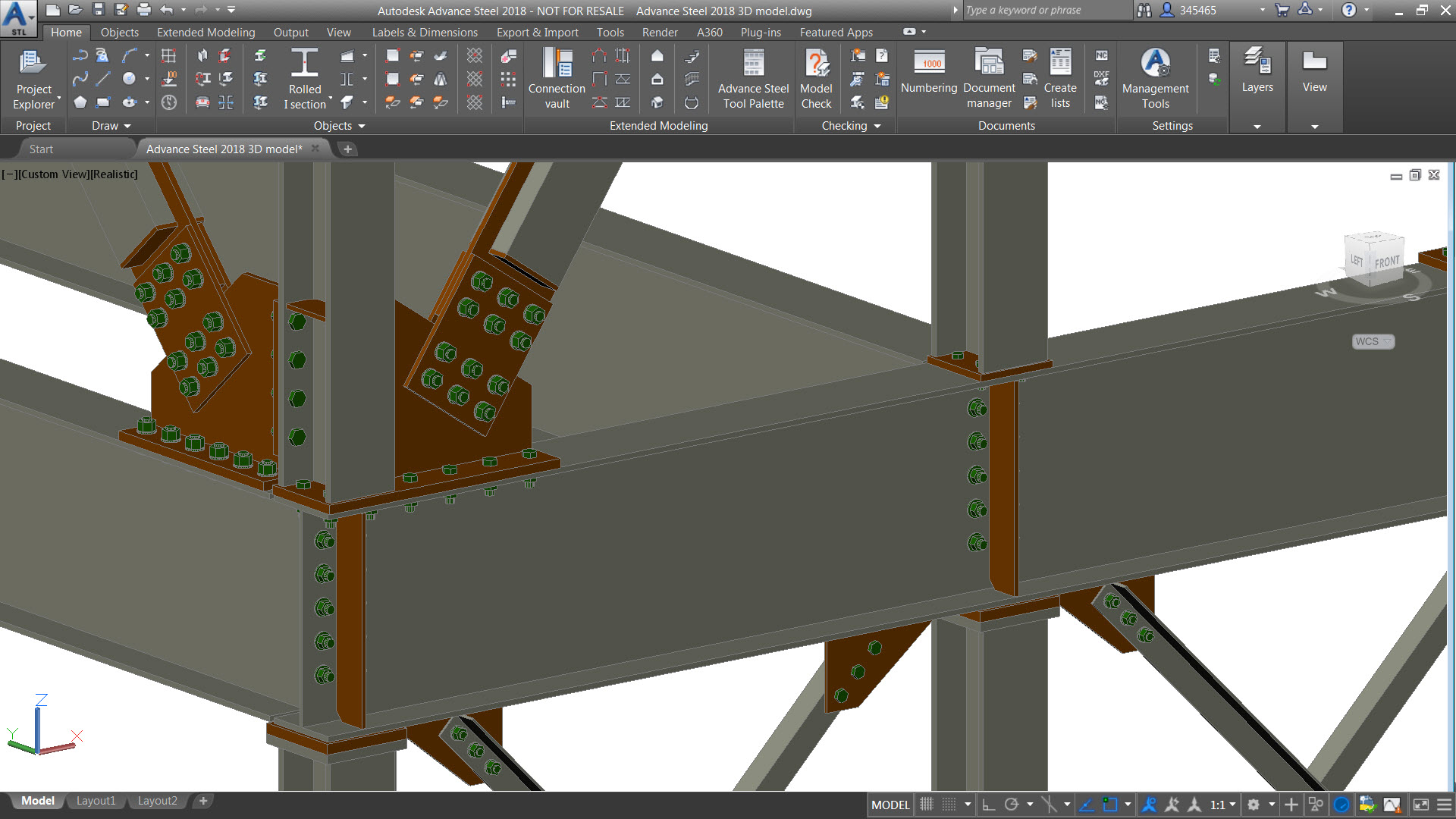
By combining the functionality of the two products into a single executable, there is no need any more for customers to separately install both AutoCAD 2018 and Advance Steel 2018 software on their desktop.

Advance Steel 2018 Installation

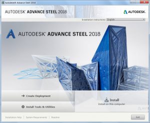
When you install Advance Steel 2018 you will see an icon for Advance Steel on the desktop. Selecting the Advance Steel icon will give the user access to the Advance Steel and embedded AutoCAD functionality.

Tip: users who would like to run just the AutoCAD functionality of the product can select ‘Autodesk Advance Steel 2018 – AutoCAD’ from the Start Menu.

2 – Migrate custom settings tool

The Migrate Custom Settings tool offers a modern and informative interface for migrating your custom settings and files from a previous release to Advance Steel 2018.

Advance Steel 2018 - Migrate Custom Settings

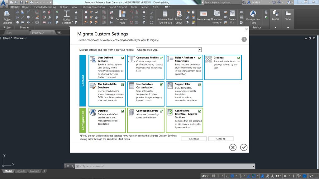
It helps detect and identify customized settings and enables you to choose which ones you would like to migrate. A summary report created from the migration offers comprehensive information in an easy-to-read format.

Tip: If you change your mind about migrating settings from a previous release, you can easily restore Advance Steel default settings using the Reset tool, which is available from the Start menu.

3 – Combine model views with cameras

Model views combined with cameras help simplify the process of creating general arrangement drawings.

Advance Steel 2018 - Combine model views with cameras

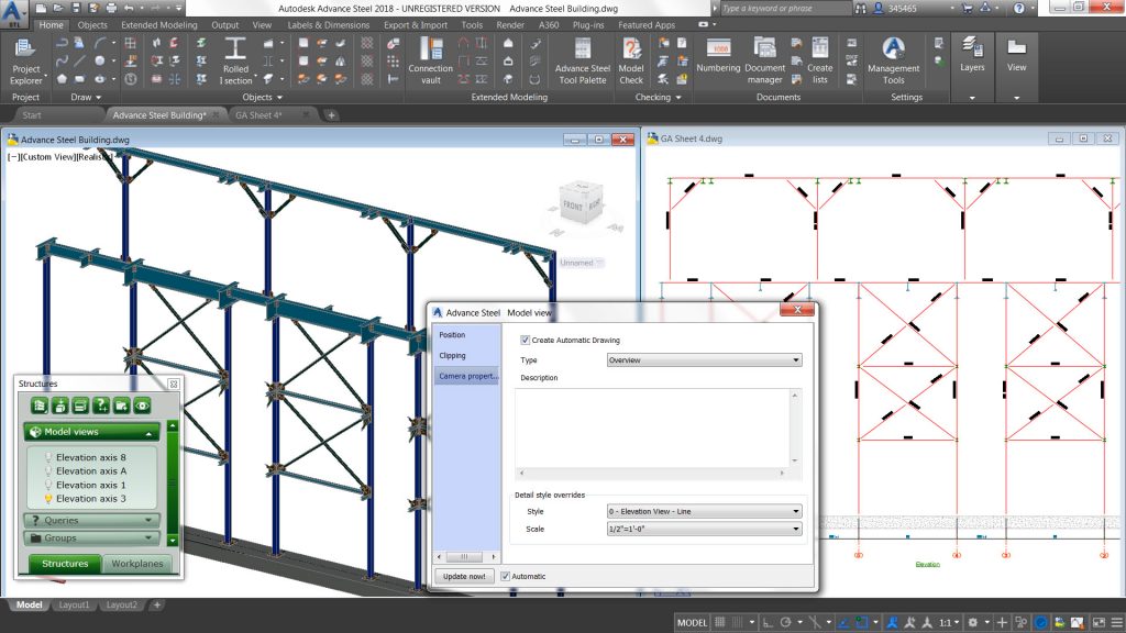
Advance Steel 2018 now enables you to combine a model view with a camera and use it for drawing creation by assigning it a specific drawing style & scale. By using a Drawing Process, you can automate the creation of general arrangement drawings based on these cameras. As a result, you get drawings automatically labelled and dimensioned based on your preferences.

4 – Call out on drawing

With the new “Create callout view” feature, you can now create a call out view from a 2D view or 3D view directly within the drawing.

Advance Steel 2018 - Call out

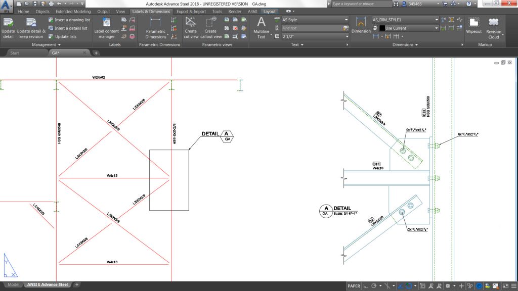
Once you have created the call out, you can move the title placement with its grip and you can control the frame appearance and change it – for example from a rectangle to a circle or vice-versa.

This new feature helps you create more compelling drawings more quickly and easily.

Tip: when creating the call out, by pressing S like Settings, you can access a dialog where you can specify the scale and assign a specific presentation to be used.

5 – Drawing styles for manual cut views on drawings

Advance Steel 2018 offers the possibility to better control ready-to-use presentations available when adding a manual cut or a call out view on a drawing.

Drawing styles for manual cut views

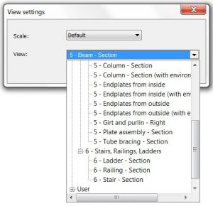
The drawing styles manager enables you to select which view presentations you would like to have available with a new option “Used for Cuts and Callouts” located under “View properties” tab.

When inserting a manual cut or a call out view within a drawing, press S like Settings to access the “View settings” dialog containing the predefined view templates and select the one you want to use for the view you add to the drawing.

6 – Enhanced local content for the US market

The weld symbol has been enhanced (text & symbol size) to match better local requirements.

Advance Steel 2018 - Enhanced local content for the US market

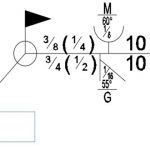
The US release is also delivered with dedicated drawing styles for shop drawings of U and C shape beams. It also has some presentation enhancement such as the hatch pattern representation for holes on shop drawings.

7 – Multi-ball stanchions handrail

Advance Steel 2018 provides a new automatic & parametric macro for inserting prefabricated ball stanchions.

Advance Steel 2018 - Prefabricated handrail

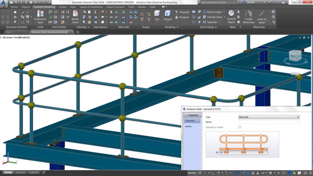
These ball stanchions are from Australian & New Zealand providers and are inserted as special parts in the 3D model.

8 – Cold rolled purlin connections

Advance Steel 2018 provides a new automatic & parametric connection for cold rolled sections (such as purlins and side rails).

Advance Steel 2018 - Cold rolled purlin connection

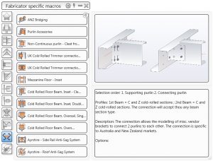
The connection can be started from the Connection vault and offers various options in regards to the brackets (from Australia & New Zealand) available by default.

Tip: It is easy to adjust the settings from the properties dialog box, you can add more vendors within the database controlling the macro.

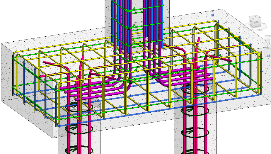
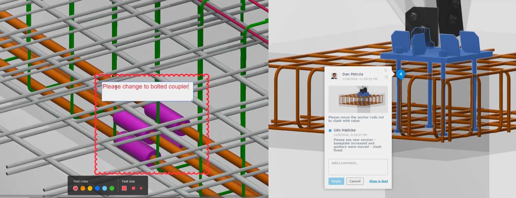
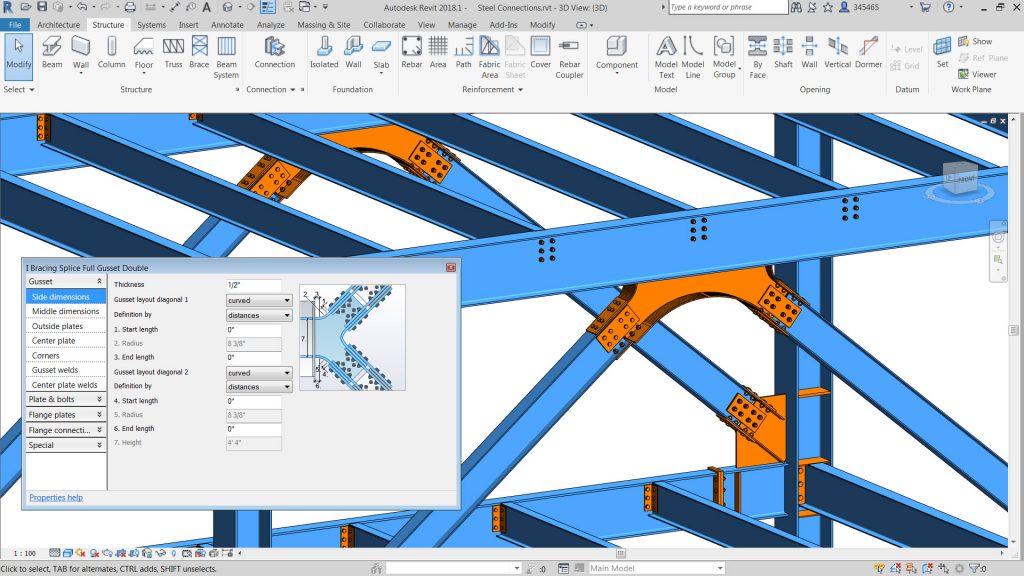
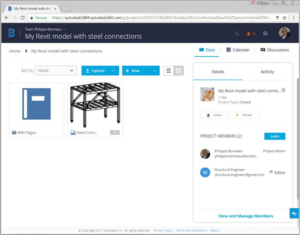
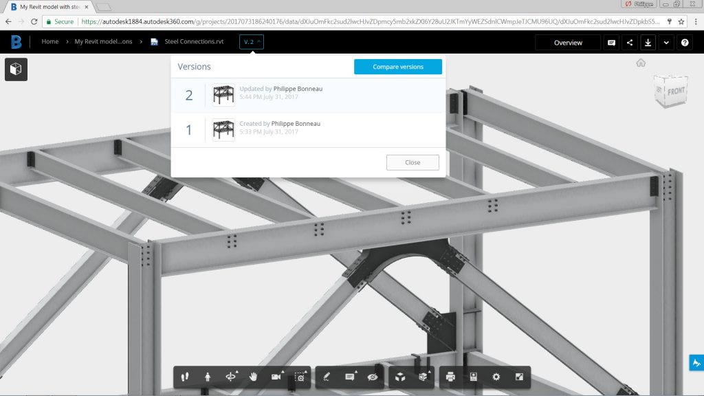
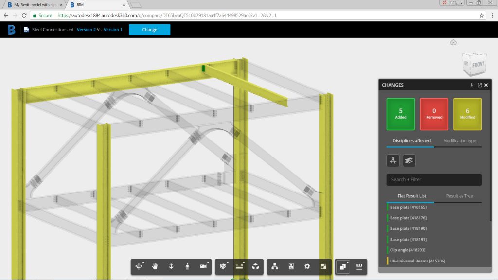
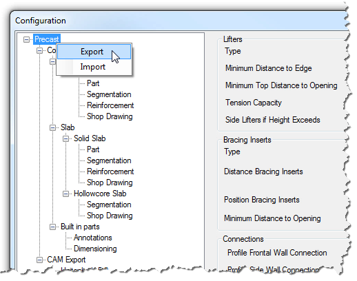
9 – Custom objects stored in the DWG file of the 3D model

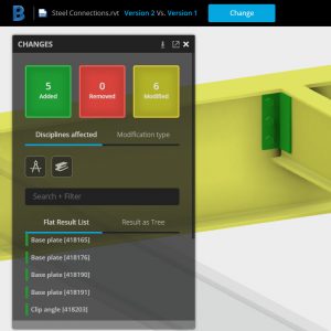
If your Advance Steel model contains custom properties such as custom sections or materials, you can choose to write this information in the DWG file so that other project team members or stakeholders can visualize the entire model in other products such as Navisworks, AutoCAD Plant 3D, BIM 360, or A360 Viewer.

Advance Steel 2018 - Store data in the DWG file

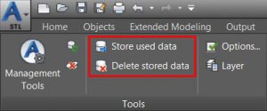
Tip: if you change your mind about including custom properties in your Advance Steel DWG file, you can use the “Delete stored data” icon available in the User Interface.

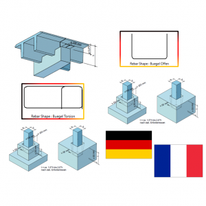
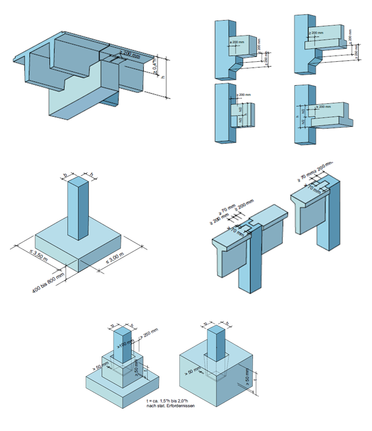
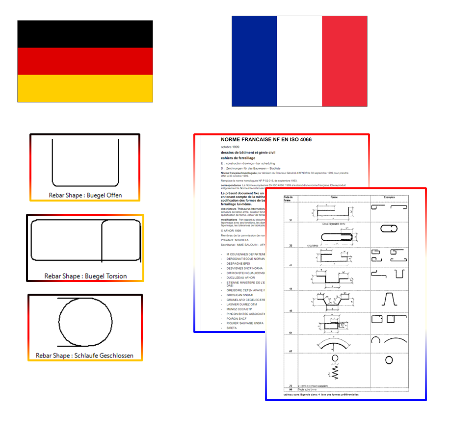
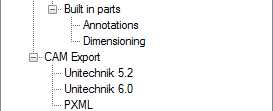
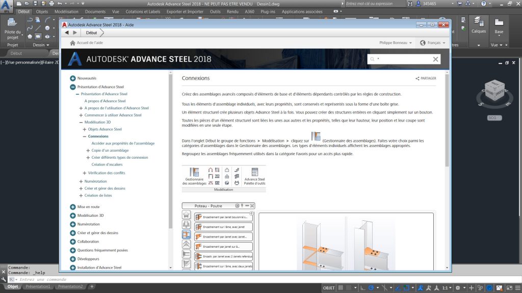
10 – Localized online help documentation

The online help documentation, which has been available only in English until now, is also available in French and German languages.

Advance Steel 2018 - Localized online help documentation

If you want to see some of these features in action, watch the Advance Steel 2018 New Features playlist on YouTube.

The post Top 10 Features in Advance Steel 2018 appeared first on BIM and Beam.


from my Autodesk source Bim & Beam: BIM and Beam at http://blogs.autodesk.com/bim-and-beam/2017/10/18/top-10-features-advance-steel-2018/
via IFTTT

Friday 13 October 2017

BIM for Reinforced Concrete – Rebar clash prevention

Rebar

This article is the continuation of a conversation that I started with the blog post depicting the value of BIM for Concrete and continued with from 2D to 3D with rebar detailing. If you’ll remember, I’ve described what I see as four main benefits for a BIM-centric approach to concrete:

  1. Combines the versatility of 2D documentation with the higher level of fidelity and accuracy of 3D modeling of steel reinforcement and concrete accessories, with minimal effort to produce both.
  2. Allows users to design and detail with rebar clash prevention in mind to reduce clashes both in the preconstruction and site execution project phases.
  3. Enables the transition from design to detailed models while respecting both perspectives, following local code requirements, and automating the process of making changes so they are less disruptive to the design process.
  4. Increases transparency and quality of the model information being used from bidding to procurement by not only providing quantifiable information, but also enabling access to it in collaboration friendly environments.

In this post, I want to focus on benefit #2, and discuss how leveraging rebar clash-detection for concrete can benefit both the preconstruction and execution phases of a project.

Benefit #2: The BIM-centric concrete solution allows users to design and detail with rebar clash prevention in mind to reduce clashes both in the preconstruction and site execution project phases.

There are many practical reasons why having rebar clashing on a construction site is highly undesired, causes serious project delays and therefore significantly increases project cost.  This can easily happen in seismic regions when large diameter rebar are used and it is not possible to resolve clashing issues by just adjusting bar shapes on site or when rebar distribution needs to be very dense as typically required for power station structures. More examples can be uncovered.

When a clash is detected, an intervention (change order) is typically sent to detailers as the finding still comes late in the design to construction process.

Clash detection tools like Navisworks can help in such situations, detecting clashes in cases where a rebar model is delivered in 3D earlier than when rebar are being fabricated and installed.

Definitely, best is when a detailed definition of rebar layouts comes already correct from rebar detailers. There are several enablers helping rebar detailers be successful and deliver clean and precise instructions for rebar fabricators and installers. Let’s name these opportunities:

Precise positioning and coordination with other objects

Precise rebar placement mechanisms mentioned above and software intelligence can guide detailers to define rebar positions with respect to all geometrical boundary conditions; both 2D and 3D snapping, increment based guiding, non-overlapping positioning with regards to rebar radiuses and diameters works as a desired clash prevention.

Precise rebar placement

Setting rebar for clash-avoiding behavior

More importantly, Revit rebar objects are born with certain intelligence respecting logic that detailers can define for it. For example, this means that we can set up rebar to behave in order to keep right distance from concrete faces, right distance from other rebar, being still adjacent to each other when rebar diameter changes, or adjust redistribution in function of changing sizes of concrete hosts, etc.

The implanted behavior makes rebar respecting detailers intent and therefore avoiding clashes as they are created and when model changes come into play.

 Constant distances in rebar for Revit

(Imposing constant distances for rebar in Revit)

What we see is what we get

As simple as it sounds, seeing rebar cages in three dimensions and with realistic sizes greatly increases a detailer’s perception and understanding of proposed reinforced concrete configurations.

Unlike with traditional shop drawings where each perspective needs to be presented in a separate view, as rebar cages are defined in Revit we can see the whole rebar cage in a single 3D view, manipulate with it, see it from all angles, and in context of adjacent model elements. All while authoring.

Dynamic 3D view in Revit

(Dynamic 3D view in Revit)

Early review and 3D model inspection

Having a broader 360 perspective with more than a single pair of eyes is usually the recommended method to secure quality for any task, rebar detailing included.

It’s amazing how easy it has become lately to share model information for a review with others.

Simply sharing the Revit model through BIM 360 makes it available via a simple link for stakeholders for inspection / review / commenting / comparison of changes. Exposing a proposed solution to others before it’s locked and stamped as rebar detailing submittals greatly increases the quality of the detailed fabrication and installation recommendations and therefore, again, makes it clash free oriented the moment it leaves a detailer’s room.

 BIM 360 Viewer Screenshots

(Screenshots from a web browser containing BIM 360 viewer)

All in all, the clash-free rebar reality is the result of a few factors: technology enablers, a detailer’s attitude, and yes … if a contractual clause specifies it as a requirement.


The post BIM for Reinforced Concrete – Rebar clash prevention appeared first on BIM and Beam.


from my Autodesk source Bim & Beam: BIM and Beam at http://blogs.autodesk.com/bim-and-beam/2017/10/13/rebar-clash-prevention/
via IFTTT

Wednesday 11 October 2017

New Structural Content in Revit 2018.2

New Precast Content

New Precast families for beams, columns, slabs, and foundations are now available.

Revit users can choose between various types of I-shape, T-shape, trapezoidal and many other beam cross sections. Columns having different corbels configurations and top supporting conditions for beams have been created. TT slabs and isolated foundations, both block and sleeve, are also part of the new Precast content.

The extended range of parameters that control their geometry allow for faster and more precise modelling of Precast concrete structures.

The German version of the families is based on Fachvereinigung Deutscher Betonfertigteilbau specifications.

The content is localized in English and German and can be downloaded from the Autodesk Knowledge Network.

This new content allows users faster and more precise modelling of Precast concrete structures.

Rebar Content Update for France and Germany

New French and German rebar shapes have been added to the Library, to enhance rebar modelling.

Among the French rebar shapes, we have also included the ones according to the older French code NF P 02 016:1993, which many French customers use throughout their projects.

The German library has been too updated with three shapes, again, to offer a complete range of rebar shapes used in this region.

The new content can be downloaded from the Autodesk Knowledge Network.

This provides enhanced rebar modelling to support better local standards.

Learn more on what’s new in Revit 2018.2.

The post New Structural Content in Revit 2018.2 appeared first on BIM and Beam.


from my Autodesk source Bim & Beam: BIM and Beam at http://blogs.autodesk.com/bim-and-beam/2017/10/11/new-structural-content-in-revit-2018-2/
via IFTTT

Tuesday 10 October 2017

Advance Steel in Autodesk AEC Collection

Advance Steel Thumbnail

Advance Steel User Interface

Structural engineers, detailers and fabricators struggle with siloed teams, disconnected workflows, and varying software platforms that do not integrate seamlessly. This requires manual processes to bridge gaps which can lead to expensive errors and fabrication waste.

To help address these challenges, we have added Advance Steel software to the AEC Collection.

AEC Collection Badge 1024p

The AEC Collection now provides structural professionals with integrated tools for a seamless, BIM-based process that connects steel design, fabrication, and construction in a more efficient and accurate way. With steel detailing more tightly linked to design, fabrication progresses more smoothly and fabricators collaborate more easily with designers and construction partners to enhance overall project quality.

Watch the following video to see how Revit and Advance Steel can work together to provide a more seamless BIM workflow from design to fabrication:

Key business benefits of the AEC Collection (now with Advance Steel):

  • Drive greater efficiency in the design process:
    • Explore different design alternatives that connect to structural analysis and BIM
    • Integrate structural analysis and design with BIM to improve the quality of the structural design
    • Provide more coordinated and accurate fabrication deliverables for estimating and production
  • Connect engineers, detailers and fabricators through better communication:
    • Coordinate across multiple disciplines to ensure a better design
    • Communicate changes between engineers and detailers more easily to reduce the impact on fabrication
    • Share the most up to date project information with the office, shop and field.
  • Reduce waste in shop and field production
    • Integrate model based deliverables with MIS software and CNC driven fabrication machines
    • Extend fabrication workflows to better plan, coordinate and execute on site
    • Optimize the detailed design to reduce fabrication and installation costs
    • Accurate BOM procures only needed quantity


We have thousands of customers worldwide using Advance Steel today. Here are a few examples of their projects:

  • New Bulgari factory in Valenza, Italy: watch out for this video
  • Louvre museum in Abu Dhabi, UAE: learn more with this customer success story
  • New operational support building at Regina Airport, Canada: discover the project by reading this article
  • The Lucas residential development in Boston, USA: check out this recent blog post
  • Imperial Beach branch of the San Diego County Library, USA, learn more on BIM & Beam

The post Advance Steel in Autodesk AEC Collection appeared first on BIM and Beam.


from my Autodesk source Bim & Beam: BIM and Beam at http://blogs.autodesk.com/bim-and-beam/2017/10/10/advance-steel-autodesk-aec-collection/
via IFTTT

Wednesday 4 October 2017

Tracking modifications in a structural steel 3D model has never been easier!

Thumbnail for compare tool - size 780 by 780

Understanding what has changed between two versions of a design is a challenge for structural engineers.

BIM 360 Team provides a tool which helps project managers, designers, and engineers better understand design changes across the different versions of a 3D model. Using this tool, users can compare two versions of a Revit file and get the differences being highlighted with color-coding.

In this example, we will be using a steel structure project modeled in Revit. The 3D model contains steel connections which have been inserted by using the Steel Connections for Revit 2018 extension, which gives access to 130 parametric steel connections, enabling connections to be modeled with a higher level of detail.

Revit model with steel connections

BIM 360 Team allows you to upload project files to enable project members to collaborate on the project. You can invite team members, just enter the email addresses of the people you want to invite and click Send Invitations. The role of project team members determines their project access level.

View and manage team members in BIM 360 Team

With BIM 360 Team, users can compare two versions of a Revit model and easily understand what was Added/Removed/Modified between the two versions.

To start using the tool, simply choose a Revit file that has multiple versions and select the “Versions” drop-down list and then click the “Compare version” button. Select the two versions to compare and wait a few seconds for both models to be loaded and their data to be compared.

Compare tool in BIM 360 Team

The Changes palette will indicate the number of any additions, removals or / and modifications. And selecting an item in the change list will highlight that object in the model view.

Change palette results

You have the possibility to turn on/off the various filters such as “Disciplines Affected” or “Modification Types” to narrow down the list of changes that you are interested in reviewing. “Disciplines Affected” include: Architecture, Structure, Electrical, Piping and Mechanical.

Disciplines affected by the changes

Information about modified object can also be displayed so that users get details on each change to understand it better.

Information dialog in BIM 360 Team

The compare tool helps understand which structural framing element and/or steel connection has been modified, added or deleted in the 3D model since its last publish.

Watch and share this YouTube video further describing the Compare Tool in BIM360 Team.


The post Tracking modifications in a structural steel 3D model has never been easier! appeared first on BIM and Beam.


from my Autodesk source Bim & Beam: BIM and Beam at http://blogs.autodesk.com/bim-and-beam/2017/10/04/tracking-modifications-in-a-structural-steel-3d-model-has-never-been-easier/
via IFTTT

Monday 18 September 2017

Structural Precast for Revit – Configuration Settings

A few weeks ago I published an overview video for Autodesk Structural Precast Extension for Revit and now I think it is the right time to get up to speed on the latest Precast tools in Revit.

With this post I would like to start a dedicated series on this new app to help you get started with the tools and to share with you some useful tips and tricks.

Autodesk Structural Precast Extension for Revit 2018 was released along with Revit 2018.1 release.

The extension must be download from the Autodesk App Store and then installed on the top of Revit 2018.1

…or you can also access the installer from within the Autodesk Desktop App:

At this moment, the extension is available in English, French and German languages.

Once installed, several Revit families and templates are placed in a dedicated location… C:\ProgramData\Autodesk\Structural Precast for Revit 2018\Families\en.

The installed files include:

  • Annotations
  • Custom slabs (sample slab families)
  • Mounting parts (lifters and other connection parts)
  • Profiles
  • Revit (rebar shapes)
  • Symbols
  • Title blocks

Here is what the Precast tab looks like once the extension is installed.

You must be wondering what the On/Off button does, an answer is pretty straight forward as it enables or disables the extension. You can use this tool to turn the extension off to replenish hardware resources and improve Revit performance if there is such need.

When you attempt to run the first command, you are presented with the following warning:

This is basically saying some content needs to be loaded for this extension to work properly.

That’s why it is a good practice to start working on a new project running the Configuration tool first.

Before you start using Structural Precast Extension for Revit you should configure these settings for walls, slabs and built in parts. The settings include position numbering, part information, segmentation rules, reinforcement definition, and project drawing defaults for walls and slabs, as well as settings for annotation and dimensioning in parts.

Once you open this dialog and click OK all necessary Revit families and templates will be loaded to the current project automatically and the warning message will not be bothering you anymore.

The Configuration dialog is organized in a tree view, each node contains options for precast concrete assemblies.

For example the wall node configures settings for solid structural walls. These settings include wall part information about lifters, bracings and connectors:

…segmentation rules:

…reinforcement definition:

…and project shop drawing defaults:

The similar groups of setting you can find for slabs (solid slabs and hollowcore slabs):

The Built in parts node configures settings for annotation and dimensioning in parts and the CAM Export node configures additional data specific to each CAM file type.

All these Precast settings are project related but you can maintain consistent configuration settings across similar projects by exporting them to an XML file which can later be imported into other projects. This gives you the ability to create different configurations for different manufacturers or sites.

To export/import your current configuration file just right click in the tree view and select Export/Import from the context menu.

In my next post of this series I will touch upon the topic of segmentation of walls.

For more posts on structural precast in Revit, check out these past articles on BIM and Beam:

@tomekf

The post Structural Precast for Revit – Configuration Settings appeared first on BIM and Beam.


from my Autodesk source Bim & Beam: BIM and Beam at http://blogs.autodesk.com/bim-and-beam/2017/09/18/structural-precast-for-revit-configuration-settings/
via IFTTT

Thursday 14 September 2017

Registration now open for the MEP and Structural Fabricators Forum 2017

FAB Forum 2017

We’ve got your back at the MEP and Structural Fabricators Forum 2017

Are you a contractor, engineer, detailer, estimator, or fabricator? Then the fourth-annual MEP and Structural Fabricators Forum is a do-not-miss event, specifically tailored to your professional and educational interests.

In one day you’ll learn current and emerging trends in Building Information Modeling (BIM), network with your industry peers, and gain expert insight from leaders in the field. We’re constantly expanding and enhancing the Fabricator’s Forum to appeal to past and future attendees, and we’ve built another full program this year.

So, what can you expect with your pass to the Fab Forum?

  1. Network with 600 of your industry peers, in one place at one time. Don’t be surprised if a single conversation leads to a new business relationship.
  2. Learn the latest trends in BIM workflows by knowledgeable technical experts who really understand your business. Check out these classes from last year’s Forum.
  3. Plan your day to fit your interests. Choose from intermediate or advanced MEP Fabrication or Structural Fabrication tracks. Participate in lecture-style business industry talks, or take a deep dive in technical instructional demos.
  4. Take hands-on labs to increase your skillset in Autodesk Revit, Advance Steel, Fabrication CAMduct, Fabrication CADmep, and Fabrication ESTmep.
  5. Get an exclusive look into what Autodesk has planned for the future of our design and fabrication solutions to help you detail better, fabricate better, and build better.
  6. Drink, eat, and network with our growing list of sponsors to include DeWalt, Victaulic, and Graybar.

Join us on Monday, November 13th for the day, or add the Forum to your registration to Autodesk University to ensure that you’re getting the most value out of your trip to Las Vegas. And don’t forget to join the conversation and tag #AU2017 and #FabForum in your social posts.

We’ll see you in Vegas!

The post Registration now open for the MEP and Structural Fabricators Forum 2017 appeared first on BIM and Beam.


from my Autodesk source Bim & Beam: BIM and Beam at http://blogs.autodesk.com/bim-and-beam/2017/09/15/mep-structural-fabricators-forum-2017/
via IFTTT

Tuesday 12 September 2017

Robot Structural Analysis in Autodesk AEC Collection

Structural engineers are using BIM to improve their design workflows and enhance collaboration with other stakeholders on projects. However, when it comes to performing analysis and design, structural engineers often face the following challenges:

  • Little time to explore the best design option due to the use of fragmented analysis and design methods
  • Insufficient coordination between engineers conducting analysis and designers/drafters modifying design models in Revit
  • Lack of integration between analysis and design models can contribute to inconsistencies in construction documentation

We also heard from our structural engineering customers that BIM-based visualization, structural analysis and fabrication capabilities have become “must haves” for their BIM workflows and for them to stay competitive.

To help address these challenges, we have added Robot Structural Analysis software to the AEC Collection. Now you can access a powerful set of tools for design, analysis, detailing and fabrication in one easy subscription.

The integration between Revit software and Robot Structural Analysis Professional facilitates the coordination of design information and construction documentation. The integration supports multiple workflows stemming from choices regarding initial modeling software and the use of multiple analytical models to split the workload. Additionally, Revit offers many tools and modeling practices to prepare a model for a smoother interoperability with Robot Structural Analysis Professional and other widely used structural analysis software applications.

The result of this interoperability is a more streamlined and productive design process, the opportunity to perform more analysis to help find the best structural design option, and a better understanding of design intent yielding less errors and omissions.

Watch the following video to learn more about this workflow:

Key Business Benefits of Robot Structural Analysis Professional in AEC Collection

Robot Structural Analysis Professional software provides structural engineers with advanced structural analysis capabilities, including for large and complex structures. Analyze models with powerful finite element auto-meshing, nonlinear algorithms, and a comprehensive library of country-specific design codes. Autodesk Robot Structural Analysis Professional is fast and flexible, enabling faster and easier structural analysis. Complementing BIM workflows, Robot Structural Analysis Professional can help customers:

  • Explore more design options that are analytically modeled and checked and linked to design models
  • Improve collaboration across BIM-enabled design teams by analyzing and incorporating changes more seamlessly to all members of the structural team
  • Design a range of structure types more efficiently with country-specific design codes and support for multiple languages and units

Using a combination of Revit and Robot Structural Analysis software, the Buro Happold team has been able to take existing design models created in architectural modeling software and develop, analyze, and optimize the structural frame of the stadium. Learn more about this story.

Image courtesy of Buro Happold


We have thousands of customers worldwide using Robot Structural Analysis today. Here are a few examples of their projects:

Concrete Structure

Design: Balt Building Engineering (Belgium)

Project: Belgian Football Federation

Mission: Use of Robot Structural Analysis for the design of a concrete structure

 
Steel bridge with custom sections

Design: IB Kwant Ingenieursbureau (The Netherlands)

Project: Lateraal kanaal, Almelo (Netherlands)

Mission: Finite element analysis of mixed wood & steel bridge, including pile foundation design.

 
Royal Theatre Ireland

Design: GGP Consult (United Kingdom)

Project: Royal Theatre, Ireland

Mission: Finite element analysis of complex public building in mixed steel and concrete structure.

 
Scissor Structures

Design: V.U.B. University, Brussels (Belgium) PhD of Lara Alegria Mira

Project:  PhD Research: “Nonlinear Analysis of Deployable Structures Comprised of Optimized Universal Scissor Components

Mission: Develop an optimized geometry using Rhino, Grasshopper and Robot Structural Analysis for advanced non-linear analysis.

 
Wood Steel bridge

Design: IB Kwant Ingenieursbureau (The Netherlands)

Project: Steel bridge, Landgraaf (Netherlands)

Mission: Finite element analysis of mixed wood & steel bridge, including pile foundation design


Also you can see what customers are doing looking at other great examples of their work by visiting the Robot forum to explore a fantastic gallery of customers’ projects.

We continue to make updates to the Robot Structural Analysis software and have recently published a hotfix for our customers.  To learn more please go here 2018.0.1 Hot Fix.

The post Robot Structural Analysis in Autodesk AEC Collection appeared first on BIM and Beam.


from my Autodesk source Bim & Beam: BIM and Beam at http://blogs.autodesk.com/bim-and-beam/2017/09/12/robot-structural-analysis-in-autodesk-aec-collection/
via IFTTT

Thursday 7 September 2017

Advance Steel, Robot Structural Analysis, and Revit Live come to Autodesk’s AEC Collection at no additional cost

AEC Collection update

Now you can access a powerful set of tools for design, analysis, detailing and fabrication in one easy subscription.

We have some exciting news for structural professionals that subscribe to the Architecture, Engineering and Construction Collection. Starting today, we’ve made some significant additions to the AEC Collection software portfolio that support the next generation of BIM—and Revit-based—workflows for building and infrastructure projects from design through preconstruction.

A Year in Perspective

Last year Autodesk moved to address your challenges by launching the Architecture, Engineering and Construction Collection as a better way for you to access the software you need for your structural projects. Our intent was to give you a powerful set of integrated BIM tools so you could be effective in your projects now, and to easily equip you with the tools needed to be proactive about what the future of designing and building has in store. With a collection including Revit, AutoCAD, AutoCAD Civil 3D, Navisworks Manage, and 3ds Max, we provided a core set of essential tools needed to make any building or infrastructure project, large or small.

Motivation Behind Today’s Big News

However, we’ve seen a change in expectations from our customers in recent months—especially our structural customers. You’ve told us that it’s expensive to try new software in order to adapt to a changing structural landscape. Specifically, you’ve told us loud and clear that BIM-based visualization, structural analysis and fabrication capabilities have moved from “nice to have” to “must have” to implement the BIM workflows you need to stay competitive.

We Heard You!

Starting today, we’re expanding the Architecture, Engineering and Construction Collection with additional tools that extend its current capabilities to support structural design through preconstruction. With these additions, and with no price change, it will be easier for you to access and implement the powerful BIM workflows you need—when you need them—by subscribing to the AEC Collection.

AEC Collection Update

What’s New

Here are some highlights of what we’re adding to the AEC Collection and what these changes need for structural professionals.

  • In the new Collection, you’ll find Revit Live. Revit Live allows you to visualize your Revit steel and concrete models by turning them into immersive visual experiences. You can even take your designs into a virtual reality environment—in just two clicks of your mouse.
  • You can now access computational design software in a greater way.  Dynamo Studio standalone programming environment can help solve challenges faster by exploring more design options and automating routine workflows of your structural designs.
  • Also included is world-class structural analysis and design Robot Structural Analysis Professional and Structural Bridge Design which work with Revit to extend your capabilities to perform structural analysis for both buildings and bridges.  These two solutions, along with Structural Analysis for Revit, can all integrate structural analysis and design with BIM to help increase productivity for structural engineers.
  • Finally, the AEC Collection now extends capabilities from structural design to fabrication. Interoperable with Revit and Navisworks, we’ve added Advance Steel to the Collection so you can conceive, model and fabricate better structural steel systems on an integrated platform. With Revit already being used to do rebar and precast detailing, structural engineers and detailers now have access to a complete set of tools for BIM-based structural design to detailing for concrete and steel.

If you want to get a feel for what structural engineers can do with the new version of the collection, check out this video that describes the workflows you now have access to.

What’s next?

For more information on what’s available in the AEC Collection, go here: https://www.autodesk.com/collections/architecture-engineering-construction/overview

Did you know that it’s also Revit’s birthday? You might enjoy reading Sylvia’s post on today’s announcement and what it means for Revit users too: http://blogs.autodesk.com/revit/2017/09/07/revits-birthday-and-aec-collection-news

And finally, if you’re a subscriber already, simply log into your My Account page to access the new software described here, and start trying out the new structural workflows that the Collection supports.

The post Advance Steel, Robot Structural Analysis, and Revit Live come to Autodesk’s AEC Collection at no additional cost appeared first on BIM and Beam.


from my Autodesk source Bim & Beam: BIM and Beam at http://blogs.autodesk.com/bim-and-beam/2017/09/07/aec-collection-update/
via IFTTT