Friday 20 January 2017

Tips and Tricks for using Autodesk Advance Steel from AU2016 (Part II)

In my last post I summarized some of the Advance Steel tips for modeling that I covered during my class at Autodesk University last fall. This post picks up where that one left off and describes the software features Advance Steel has for helping you create and manage documentation more effectively.

Here we go!

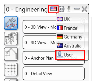
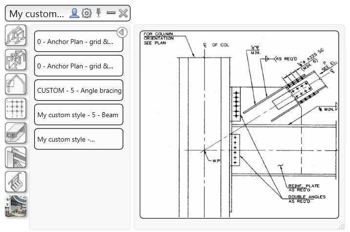
1. Getting access to your customized templates

You can easily switch between templates delivered out of the box when installing Advance Steel (from the Advance branch) and templates from the User branch (which contains your customized templates) with the “User” icon located at the top of the palette. The same behavior applies for the drawing styles, drawing processes and BOM templates tool palettes.

Advance Steel tips for customized templates
Advance Steel tips - getting access to customized templates

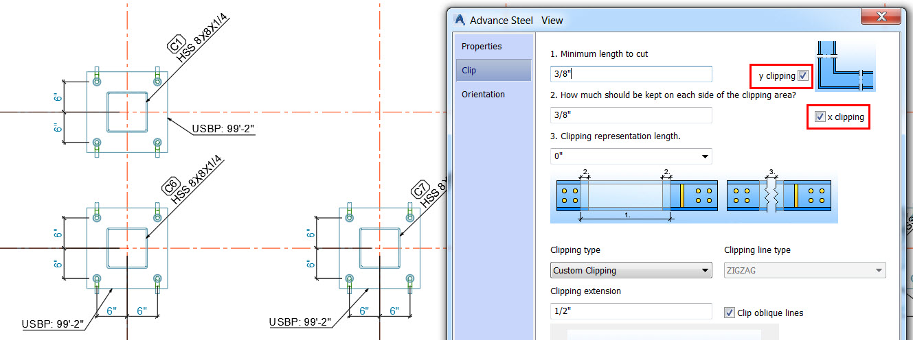
2. Increasing column size on anchor bolt plan

You can get details bigger on your anchor bolt plan by modifying the view scale and changing the clipping values along X and Y. This makes anchor plan drawings easier to read, and ensures steel details are more practical with enlarged information for the columns shape and orientation, but also the base plates layout.

Advance Steel Tips for increasing column size on anchor bolt

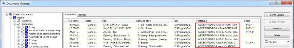
3. Finding information on used prototypes

Drawing prototypes are blank drawing sheets that are used to create the shop drawings and general arrangement drawings. An easy way to find which prototype has been used for a drawing is to look on the Document Manager, the information is available in the “Prototype” column.

Advance Steel Tips on finding information on used prototypes

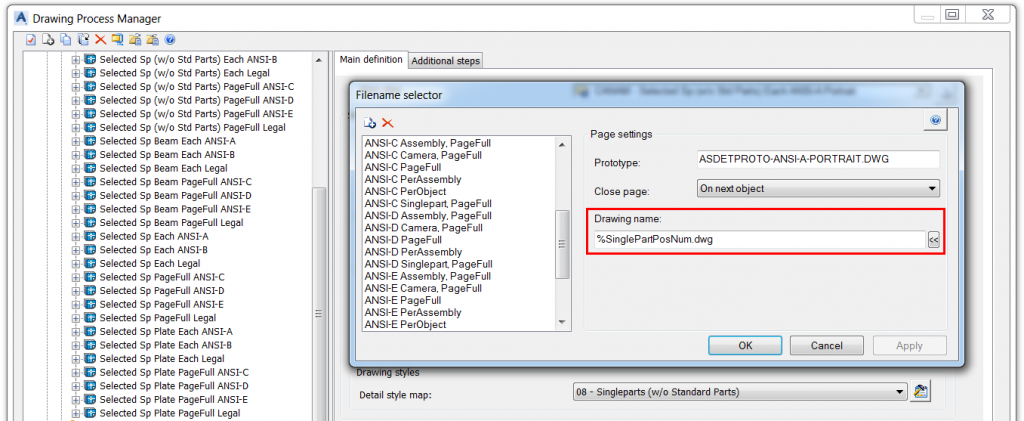
4. Customizing shop drawing file name

When creating the shop drawings, it is a good practice to use a drawing process which will step through all of the selected objects, selects a suitable drawing style, creates the shop drawing of the object, and moves on to the next object. In this way many drawings of many objects can be created quickly and easily. The drawing process manager offers the possibility to customize the shop drawing name according to your needs.

Advance Steel tip on customizing shop drawing file name

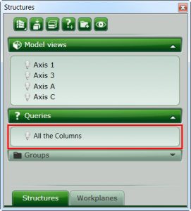
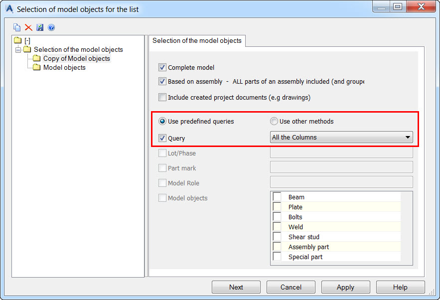
5. Creating a bill-of-material based on a query

You can create a query (e.g. search for Advance Steel objects which model role is “Column”) and by saving it, the query will become available in the Project Explorer so that you can run it at any time. What is great is that you can use this query to generate a BOM only for elements selected by this query.

Advance Steel tip on creating a BOM queryAdvance Steel tip on creating a BOM query

If you’re interested in watching the full class on-demand, visit Autodesk University online here:

For more tips on using Advance Steel, check out these previous blog posts:

The post Tips and Tricks for using Autodesk Advance Steel from AU2016 (Part II) appeared first on BIM and Beam.


from my Autodesk source Bim & Beam: BIM and Beam at http://blogs.autodesk.com/bim-and-beam/2017/01/20/advance-steel-tips-from-au2016-part-ii/
via IFTTT

7 FORMS OF DEFECTS IN PLASTER

TYPES OF DEFECTS IN PLASTER This post describes 7 different categories of defects most frequently noticed in plaster (as mentioned below) Non-structural cracks Structural cracks Debonding Lack of hardness Grinning Expansion Popping The causes and repair methods for each are discussed below. 1. Non-structural cracks Crazing is a network of fine cracks, usually in a […]

The post 7 FORMS OF DEFECTS IN PLASTER appeared first on CivilBlog.Org.


from CivilBlog.Org http://civilblog.org/2017/01/20/7-forms-defects-in-plaster/
via Our favorite Civil Engineering Blog

Thursday 12 January 2017

Stepped Reinforced Concrete Foundations in Revit

Stepped Reinforced Concrete Foundations

In the Revit content you can find a reach pallet of Structural Families preinstalled. In the Metric UK Library you can find the Structural Foundations folder which contains the number of different foundation types: a pad footing, a strip footing, a pile cap etc.

Structural Foundations Families

Recently my colleague asked me: “OK Tomek, I have all these families in that folder which is fine but what about a pad foundation which is stepped? I can’t find such family in the folder so how can I model it in Revit?”

Pad foundations are used to support an individual point load such as a structural column. They may be circular, square or rectangular. They usually consist of a block of uniform thickness, but they may be stepped or haunched if they are required to spread the structural load from a heavy column. Pad foundations are usually shallow, but deep pad foundations can also be used.

My colleague was right. The folder consists of the Footing-Rectangular.rfa family which is not a stepped one but this family can be easily adjusted by any Revit user, saved as the Stepped Footing-Rectangular.rfa and used in future projects.

Families are an integral part of working in Revit, and the key to creating custom content. Creating your own families is a great way to build a library of custom content.

In the next serious of steps I would like to show you how to create a stepped pad foundation.

Rather than start from scratch I am going to use the existing Footing-Rectangular.rfa family as my starting point.

1. Edit Family and open the Family Editor. The Family Editor is a tool to create new families or make changes to existing families.

02

2. Go to the Level and create additional reference planes. Reference planes give our family its structure and we will use the new ones to create a new foundation block.

Reference plane

Create Reference Planes

3. Add dimensions to each group of reference planes. Two vertical and two horizontal. There should be an overall and a continuous string including the centerline in each direction.

 Add dimensions to each group of reference planes

4. Select each of the continuous strings and toggle on the Equality.

Equality

5. Select the new horizontal overall dimension. On the ribbon, next to the Label drop-down, click the small Create Parameter.

Create Parameter

6. In the “Parameter Properties” dialog that appears, name the new parameter: Width 2, choose the Type radio button and click OK.

Parameter Properties

7. Repeat this for the vertical overall dimension and name the new parameter: Length 2.

8. With a good framework in place, it is time to add a solid form to the Family. On the Create tab, click the Extrusion.

Extrusion

9. On the Modify | Create Extrusion tab, on the Draw panel, click the Rectangle Snap to the intersection of two of the reference planes for the first corner, and then snap to the opposite intersection for the other corner.

Create Extrusion

10. It’s time to do a test of what we have done so far. When you test your flexible family, it is called “flexing” the model. On the ribbon, click the Family Types.

Flexing

11. Input a different value for all the Width, Width 2, Depth and Depth 2 fields and then click the Apply button. The locations of the Reference Planes should adjust but stay equally spaced from the center. The block geometry should update accordingly.

12. Now it’s time to take care about the height of foundation. In the Front view, select the box. Drag the triangle shape handle grip at the bottom. Lock the top of the new box with the bottom of the existing one.

Height of foundation

13. Add a new dimension.

Add a new dimension.

14. Assign parameters to the newly created dimension (Foundation Thickness 2).

Foundation Thickness 2

15. Go to the 3D view and flex it again. On the ribbon, click the Family Types Click Delete Type to remove one of the existing types. Click the Rename Type and call it: Foundation 1 and then click OK. Set up parameters to test your families.

Family Types

16. If everything works properly it’s time to assign a material parameter. Select the block and click the Associate Family Parameter button and then select the Structural Material parameter and click OK.

Associate Family Parameter

Associate Family Parameter

Associate Family Parameter

17. Now you can save your family as Stepped-Footing-Rectangular.rfa and load into your project.

Stepped-Footing-Rectangular.rfa

18. The rest is rebar detailing 🙂

Stepped Reinforced Concrete Foundations


The post Stepped Reinforced Concrete Foundations in Revit appeared first on BIM and Beam.


from my Autodesk source Bim & Beam: BIM and Beam at http://blogs.autodesk.com/bim-and-beam/2017/01/12/stepped-foundations-in-revit/
via IFTTT