For a library project in a California beach town, 3D modeling using Revit and Advance Steel workflows helped a design-build project team deliver a challenging but symbolic design on an accelerated timeline.
When architects delivered renderings for a 14,380-square-foot library facility in Imperial Beach, Calif., local stakeholders praised the design for its seamless fit with the small San Diego County beach city.
San Diego firm Jeff Katz Architecture developed the design after county officials spent three years gathering local input, and the firm took great care to create an informal and flexible library space that would foster community pride. The building’s signature design element is a curved roof that mirrors a breaking wave, with the library’s floor plan designed around the wave structure. The local newspaper applauded the design for its “beach town feel,” and local officials said the plans “really captured the essence of a small beach community.”
But that signature wavelike roof would later briefly threaten to slow down the entire project when, due to circumstances beyond control, the team faced a tightened timeline to complete the building’s steel detailing. Lance Richardson, chief operating officer of Spring Valley, Calif.-based Richardson Steel Inc., brought Bart Rohal, president of Colorado-based Steel Detailing Online Inc., onto the project in late January 2016, giving Rohal only about a month to submit the steel detailing work without causing project delays. This would have been difficult for a project with a more-traditional design, but the curved roof brought its own, additional challenges.
“It’s really easy to build big square boxes,” says Richardson. “But when you have a roof that is elliptical in nature, the geometric challenges are many. The manner in which the steel has to provide a framework for all of the other trades and finishes requires a lot of precision, and it’s more difficult to be precise along an ellipse.”
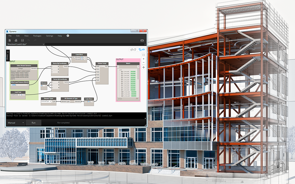
Richardson reached out to Rohal in part for his overall experience, but also his specific expertise with 3D modeling and detailing software. Since 2011, Rohal has been using Autodesk’s Advance Steel detailing software, which is interoperable with models produced via Autodesk Revit. Building information modeling (BIM) was a requirement of the library project, but perhaps more importantly, the process helped accelerate the steel detailing and fabrication processes, which prevented potentially costly delays.
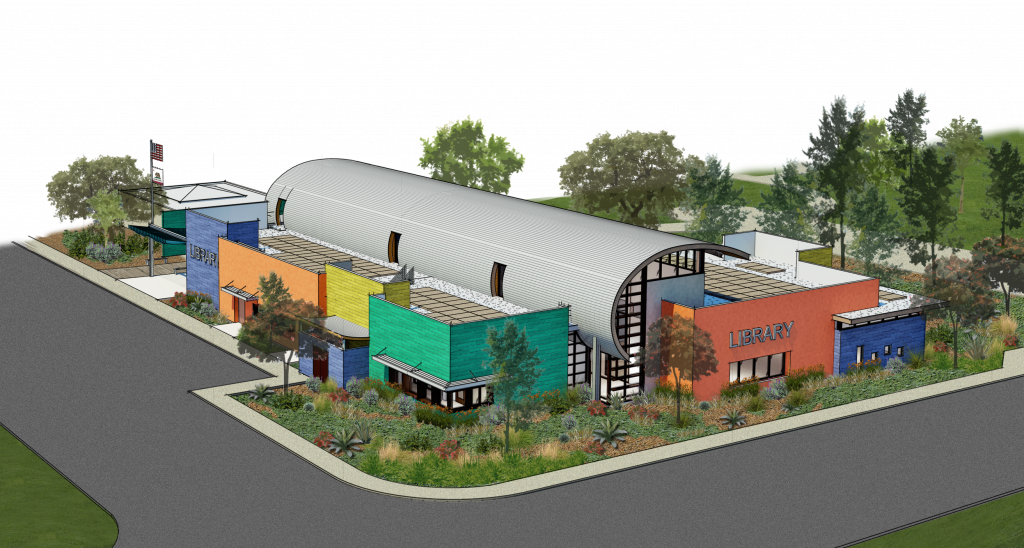
Architectural rendering of the Imperial Beach Library showing the ‘wave like’ curvature of the roof.
Rohal calls the wavelike roof shape “unique.”
“A lot of times, we’ll do radiuses, but it’s usually a continuous radius,” notes Rohal. “This required three different rolled-steel sections with three different radiuses to get the right look.”
Rohal initially estimated that the steel detailing for the project would take between six and eight weeks. “I think they wanted it done in four,” he says. “But I was just going to get it out as soon as possible, and get it done correctly. I’ve been doing this for 35 years. You don’t want the pressure getting to you.”
The Project
Since 1966, the Imperial Beach branch of the San Diego County Library system operated out of a 5,100-square-foot county-owned building on Imperial Beach Boulevard. The new library project, a partnership between city and county, included demolition of that structure along with the design and build of the new library building, which will have space for library materials, programs and resources at the same location.
The library entrance floor, made of decorative concrete with a sandy look, will contribute to the building’s beach feel and extend from a boardwalk through the library and toward the back of the building, where it will transition to carpet-tile, mimicking the appearance of a shoreline. The interior is designed to mirror a beach-cottage living room, and the exterior will have a combination of stucco and colored porcelain, evoking a series of beach cottages.
Using Revit, the design team created a 3D project model. Rohal then used the 2D contract drawings, with the help of the 3D Revit model, to bring the Advance Steel construction model for the project to Level of Development (LOD) 400 (with the exception of the stairs, which were handled by another detailer). The LOD specification allows BIM practitioners to work from a common reference point when it comes to the content and reliability of BIM models. Using the BIM Forum’s definition of LOD, Rohal’s LOD 400 model contained sufficient detail and accuracy for fabrication of the structural steel frame.
In addition to the wavelike rolled-steel roof, the design called for wide flange columns and beams, moment connections, rod bracing with clevises and turnbuckles, and architecturally exposed rolled channels in the entry area with a 204-foot radius. Beam-to-beam and beam-to-column connections mostly consisted of bolted shear plates, with custom seated connections between the rolled steel and supporting columns.
BIM Benefits
Although some people have been doing 3D modeling for years, different design teams and detailers have different levels of comfort with software programs such as Revit and Advance Steel (and some still haven’t adopted them at all, which can result in lost work when, as in this instance, BIM capabilities are required for a project). Rohal has been using 3D modeling for more than half a decade, but he says it’s uncommon for design teams to send him a 3D project model to assist with his detailing work, except for BIM-implemented projects such as the library.
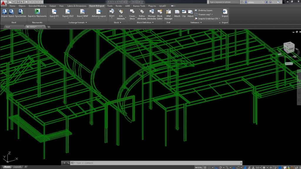
An Advance Steel view of Revit LOD-200. For this project, the Revit model was used as a cross reference to move the Advance Steel model to LOD 400.
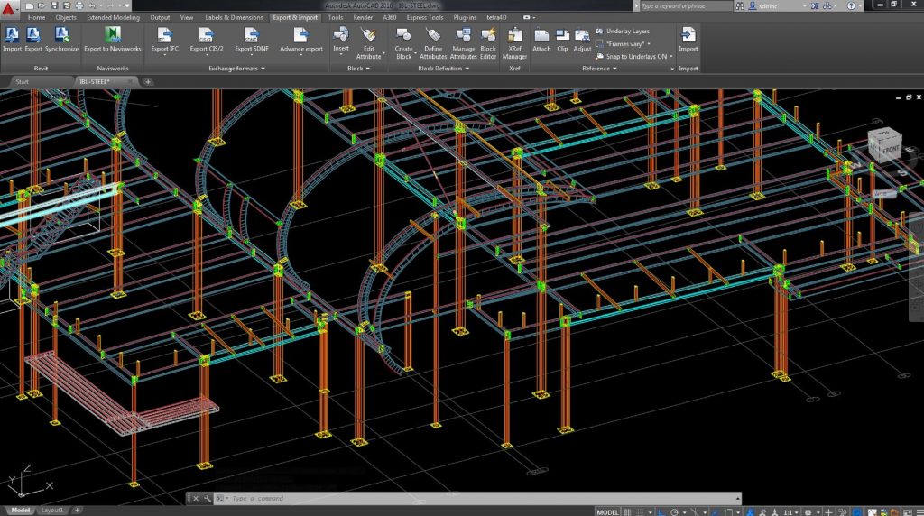
In this model view, the final Advance Steel model is seen at LOD 400.
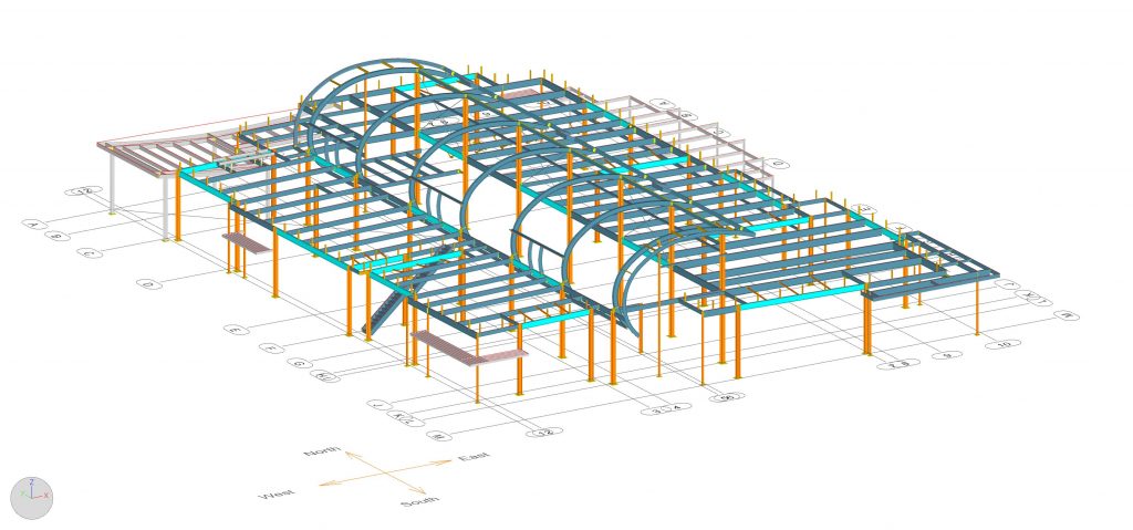
The Advance Steel ISO view shows the structural steel in LOD 400. Gray is galvanized steel, and light cyan indicates moment beams.
According to Rohal, some design teams that use BIM don’t always share their models with him. But he sees this changing as LOD-based workflows help establish a common language for model-based exchanges as teams move between the design, detailing and fabrication phases of a project.
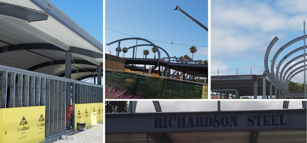
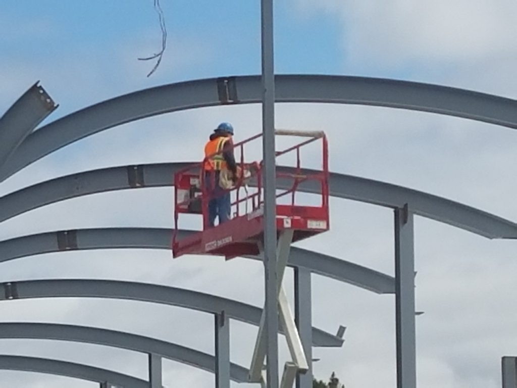
Photos show the final, fabricated steel beams for the wave-like curved roof being installed by Richardson Steel.
In constructing his 3D steel detailing model with Advance Steel, Rohal relied primarily on the 2D drawings from T.B. Penick and Sons Inc.—these served as the project’s official governing contract documents. Still, he says, it was valuable to have the 3D Revit model from the design team, as he was able to import this model into Advance Steel as an external reference (xref) and use it as a guide for his work.
“I inserted the 3D Revit model into position, and then I built my Advance Steel LOD-400 model on top of it,” explains Rohal. “I used the 2D drawings as much as possible and then turned the 3D Revit model on and off as needed.”
The potential downside of working from a 3D designer model is that if the model is in any way outdated or inaccurate, then the steel detailer risks following those older designs during the steel detailing process, unless he or she also checks the work against the 2D contract drawings.
“You only want to use the model as a reference,” adds Rohal. “In this project, I had to use the model at my own risk, but in my years of modeling experience, I’ve found that it’s good to have that Revit model from the designer, if available.”
In addition to helping him visualize the building’s complexity, the 3D Revit model helped speed up the Advance Steel modeling process by aiding in his interpretation of the 2D contract drawings. When Rohal had a question, he could often figure out the answer by analyzing the 3D Revit model, rather than submitting a formal request for information (RFI) to the general contractor.
“There are very few jobs that go through with zero RFIs,” notes Rohal. “In this case, the 3D model helped eliminate some RFIs, because it helped me interpret the 2D drawings. There are times in the drawings where I’d say, ‘What is the architect and engineer trying to get across here?’ When you have a design team model, you can just rotate it and zoom into the exact spot you’re looking for. You can think of a model as almost infinite pictures.”
In addition, the 3D Revit model was essential when it came to modeling in Advance Steel the roof’s unusual wavelike structure, which featured three different radiuses. Due to the project’s design-build nature, subcontractors such as Rohal were given more input than usual, and the Revit model helped him interpret the design team’s intent for how the roof’s steel should ultimately be erected.
For steel detailers, the migration toward 3D modeling software is gaining steam, as more fabricators are requesting model-generated computer files, and more project owners are requiring BIM capabilities of their contractors.
“In a more-complex building, I think [BIM] offers more benefit,” adds Richardson. “You model in all of the different construction trades, and you’re able to identify physical conflicts in the model before you identify them in construction, and that can prevent delays. The geometry was complex enough that I think the BIM modeling was worthwhile on this project.”
A Collaborative Process
Even with the 3D Revit model as a reference, Rohal still generated several dozen RFIs during the steel detailing process. “If I send in 40 or 50 RFIs, that can take weeks for the design team to respond, and we didn’t have that time,” says Rohal. With time at a premium, Rohal worked with Richardson Steel, T.B. Penick and Sons, and the architecture and engineering team to clear up the RFIs as quickly as possible.
While modeling the project in Advance Steel, Rohal used Navisworks Simulate to create viewpoints and RFIs, and he then developed a viewpoint log in Navisworks to track records of comments. During a virtual team meeting, Rohal was able to get answers to each of his questions in a single two-hour session, and then print out and send a record to all members of the team. “That kind of collaboration expedited the whole project,” he says.
When Rohal finished the Advance Steel construction model for the library, he uploaded the Navisworks NWD file to a file-sharing service, in addition to Autodesk BIM 360 Team, giving the entire project group access to the 3D steel model with a click of the mouse on a browser. These files included all BIM data from the detailing and helped the design team visualize complex areas, along with steel weights and marks, in an interactive 3D model. Critical items such as galvanized steel were color-coded for easy recognition. Rohal calls this feature a “virtual jobsite walk, but with BIM information.”
Steel detailing through BIM programs such as Advance Steel also can facilitate a faster and smoother fabrication process. For this project, Richardson didn’t rely on Computer Numeric Control (CNC) codes, because the building’s unusual geometry meant there weren’t many repeated parts. However, Richardson says, CNC-aided fabrication from software products such as Advance Steel that can automatically export CNC files can “speed up production quite a bit” on many projects.
In this instance, the material reports generated via Advance Steel were particularly helpful. “The Imperial Beach Library structural steel went up beautifully,” says Richardson. “Not a single hole had to be reamed. Additionally, I saved at least 80 management hours through use of the materials reports. I was able to edit or modify the reports for different applications for procurement, separation of galvanized and painted members, roll-forming, and shipping to site.”
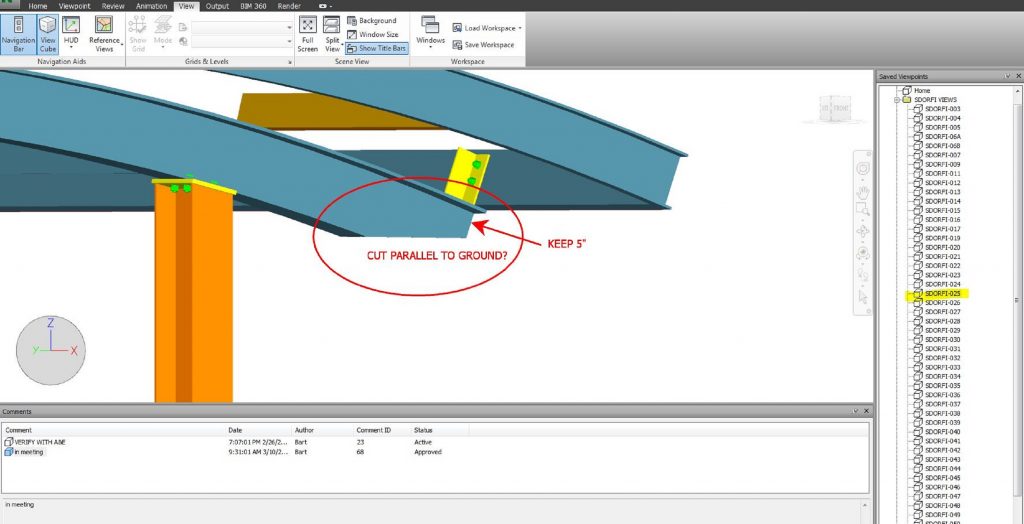
The team created a Navisworks model from Advance Steel to populate all RFIs as well as use for online team meetings to quickly resolve issues and submit formal RFIs or ROCs (records of conversations) to keep the project moving.
The Results
Rohal initially estimated that the steel detailing for the library project would take between six and eight weeks, but the efficiencies of the BIM process and the collaborative efforts of the project team ultimately allowed him to create the full 3D construction model and submit the first phase of 2D paper drawings in about five weeks. Although the model allowed Richardson to order the steel for the library project, it wasn’t until the first phase of 2D paper drawings were completed and submitted for approval that he was able to begin fabrication of the columns. After this first phase, it took Rohal approximately two more weeks to complete 2D paper drawings for the building’s beams and rolled radiuses, which cleared the way for fabrication of the remaining steel.
“Oftentimes, I ask for the stars in hopes of getting the moon,” adds Richardson. “If I asked for [the detailing] in four weeks, I certainly knew that [Rohal] wasn’t capable of doing it in four weeks. But he stayed ahead of the project, and I think he delivered well.”
Richardson says there “most likely” would have been project delays if Rohal hadn’t been able to come through in such a timely manner, possibly leading to an assessment of liquidated damages. “The sooner detailing is complete, the sooner the design team can review it, and the sooner fabrication can begin,” he adds. “In a steel-frame building, if the steel isn’t onsite, pretty much no one else is working, either.”
The post Coastal Library ‘Rides the BIM Wave’ with Revit and Advance Steel workflows appeared first on BIM and Beam.
from my Autodesk source Bim & Beam: BIM and Beam at http://blogs.autodesk.com/bim-and-beam/2017/02/06/coastal-library-rides-bim-wave/
via
IFTTT