Several years ago, Lawton Welding Co. Ltd., a miscellaneous metals and small structural steel company based in Topsfield, Massachusetts, took on a project detailing and fabricating the steelwork for an old stone church that was being renovated and repurposed. The project was fraught with rework orders — largely due to the irregularities of the stone structure — and took nearly three months to complete.
More recently, Lawton tackled a similar – but much larger – project, detailing and fabricating the steel for a former church in downtown Boston. The late-1800s stone structure, which was being converted into eight stories of condominiums, presented many of the same challenges as the previous project. Lawton finished the newer project in around six weeks.
The difference? In the interval between the two projects, Lawton gained the ability to detail steelwork in three dimensions by adopting Autodesk Advance Steel detailing software.
“This project was probably ten times bigger than the previous one, and we got it done in less time,” says Derek Michaud, detailing supervisor at Lawton. “With this one, we had almost no rework. Before, I would get frantic phone calls from my install crews when changes were needed,” Michaud adds. “In the new system, you make the change, and everything automatically moves with it. It’s a much cleaner process. It’s night and day.”
The Project
The Lucas, an 80,000-square-foot development located in Boston’s South End and designed by Finegold Alexander Architects, is the transformation of an 1874 German Trinity Catholic Church into a unique residential development.
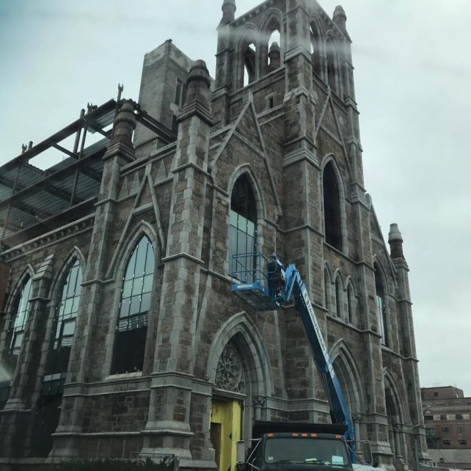
Before it was high end residential housing, The Lucas was an 1874 German Trinity Catholic Church. Image courtesy of Lawton Welding, Co., Ltd.
The design maintains the church’s existing puddingstone façade and exterior walls, but also places a new eight-story building in the center of the church’s footprint. The glass and steel rising up from behind the original stone creates a dramatic visual contrast, but it also presented formidable challenges for Lawton’s detailing team.
“The design makes things far more complicated, because we have to interact with the existing structure,” says Michaud. “On a new building, you control everything. If a column is off by a quarter inch, all my steel matches that column no matter what. In existing buildings, you don’t have that luxury. You have to be close enough to the walls, but not hit them. You can’t be too far away, because then you don’t get the performance of the design.
Rapid Return on Investment
One of the chief benefits of adopting 3D detailing software, Michaud says, is the dramatic time savings that the new method enables – at nearly every step of the detailing and fabrication processes. “It allows us to do more work in the same amount of time, without increasing payroll,” Michaud says.

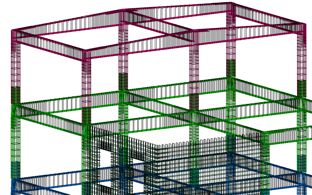
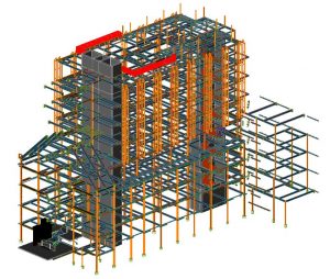
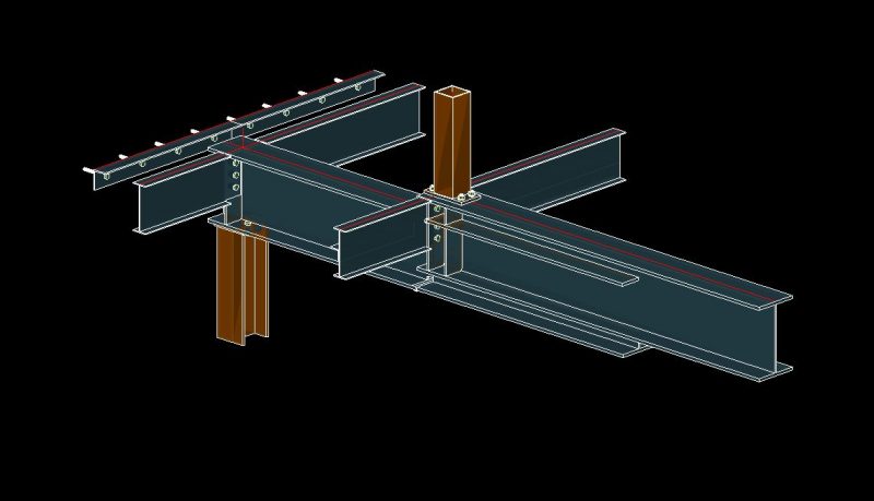
3D model of the steel frame for The Lucas residential development in Boston’s South End. The development is a renovation and reimagining of the original structure. Image courtesy of Lawton Welding, Co., Ltd.
Not only does the detailing work itself go more quickly in Advance Steel, but the software also prevents employees from having to double back over their work to fix mistakes. Additionally, Advance Steel automatically generates computer numerical control (CNC) fabrication files, eliminating another time-intensive step.
On The Lucas, Lawton shared its detailing plans with the project’s plumbing and HVAC contractors. These contractors then told Lawton where in the beams to put additional holes. Consequently, Lawton was able to cut the holes in the fabrication shop, rather than sending employees out to do the work in the field.
Improved Accuracy
One number, more than any other metric, illustrates the impact of Lawton’s move to Advance Steel: 10 percent. That was the firm’s average error rate on the steel it fabricated before making the switch. Today, Lawton’s error rate has dropped to under 1 percent. Michaud estimates that the firm has an error on only one or two out of every 250 beams produced.
“With so many human steps, holes would be off all the time,” Michaud says. “We would drill holes, check the layout, and then we would have to fill the holes back in and re-drill them by hand. That was a constant problem.”
“All of that is on us,” he adds. “Any fabrication error, any material waste, all of that is 100 percent on us. You can damage a profit line pretty quickly if you’re not careful.”
Before Lawton made the switch, Michaud says, there was little standardization in fabrication drawings, which contributed to the higher error rate – and to frustration on the part of the fabricators. “We had seven guys who drew seven different ways,” Michaud says. “Now our drawings all come out exactly the same. Our fabrication shop likes it better, and we no longer have errors being calculated by humans along the way.”
The software also helps prevent connection problems by allowing detailers to better see how their drawings will work in the real world. “Working in three dimensions allowed us to visually see everything, to make sure we had room for bolts, to make sure the plan was strong enough before we sent it to our engineer. We saved time on our engineering re-design work, and everything fit together smoothly.”
On The Lucas, detailers needed to draw around the existing walls, which bowed in and out at various spots. A field crew provided a three-dimensional survey of the interior walls, and Lawton imported that data into Advance Steel, allowing detailers to draw with precision down to a quarter of an inch. This level of precision, Michaud says, helped to drastically reduce rework.
The Power of BIM
On The Lucas project, architects didn’t provide Lawton with a three-dimensional design model from a building information modeling (BIM) software such as Revit. If the firm had started with such a model, Michaud says, the detailing would probably have gone even more quickly. “If we would have started with a Revit model, we probably would have cut about a week off,” he says.
Increasingly, Michaud says, BIM tools are becoming an industry standard. “A lot of the companies we work with now require BIM compatibility,” he says. “If you can’t draw in 3D, you can’t even quote the job. It’s definitely giving us an advantage.”
Steel detail of a kinked beam in Autodesk Advance Steel. Image courtesy of Lawton Welding, Co., Ltd.
Tools like Advance Steel not only help Lawton win more jobs and complete those jobs more quickly, but Michaud says that BIM solutions also reduce stress on him and his workers while increasing client satisfaction. On The Lucas project, for example, concrete anchors were placed an inch and a half off from where they were supposed to be, requiring Michaud and his team to make that same shift in the plans for the entire project.
“We had to move the whole building an inch and a half, right before we started fabricating it,” Michaud recalls. “With Advance Steel, we were able to do that in twenty minutes. In two dimensions, it probably would have taken one or two days, and then we would have had to hope that we didn’t make a mistake during the rush. We definitely would have missed our install date.”
“With BIM,” Michaud adds, “it’s amazing how smooth and how fast things can go.”
The post Steel and Stone: Autodesk Advance Steel helps structural steel company reduce schedule by 50% appeared first on BIM and Beam.
from my Autodesk source Bim & Beam: BIM and Beam at http://blogs.autodesk.com/bim-and-beam/2017/08/17/lawton-welding/
via
IFTTT