
In this post of the Structural Precast series I would like to show you how in Revit we can easily add grout tubes and tubes on top to precast walls.
Grout tube and tube on top are families that come with the installation of Structural Precast Extension for Revit. They are both face-based families. When modeling you can use them or your own families.
In Revit, there are a few ways how these elements could be added to precast wall assemblies.
First, I would like to show you a traditional, manual way.
- We simply start the Place a Component command.

- Then select a family and a type.

- Next select a wall face. Note: Orientation of grout tubes depends on which side/surface of a precast wall has been selected.

- Then a position of these elements can be further adjusted using built-in Revit capabilities. For example, you can specify a distance from the edge, distance between elements, use copy or mirror tools etc. …

As you probably noticed already the process itself is pretty straight forward however it can be very tedious and it takes a lot of time as we need to do the same for every single precast wall instance.
This is a situation where Dynamo for Revit comes in handy. Let me show you my automated process of adding tubes to the Revit model.
I made a few assumptions:
- My Dynamo script should be ready to be use in Dynamo Player.
- It should work with multi-selection of precast walls.
- Input parameters should allow selection of types of elements as well as their precise placement.
As a result I ended up with a Dynamo script with the following input parameters in Dynamo Player:
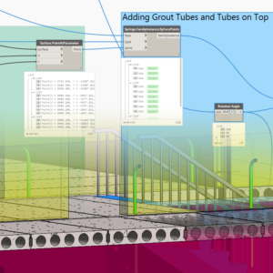
 Let’s have a look inside the Dynamo script. First, I need to retrieve selected faces.
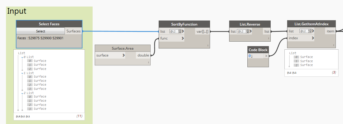
Next, I have to check the orientation of my faces.

My Python script checks if the beginning of local coordinate system of my surfaces is at the top or bottom and it calculates a rotation angle for grout tubes.


Now it’s time to get information about lengths of my wall parts.

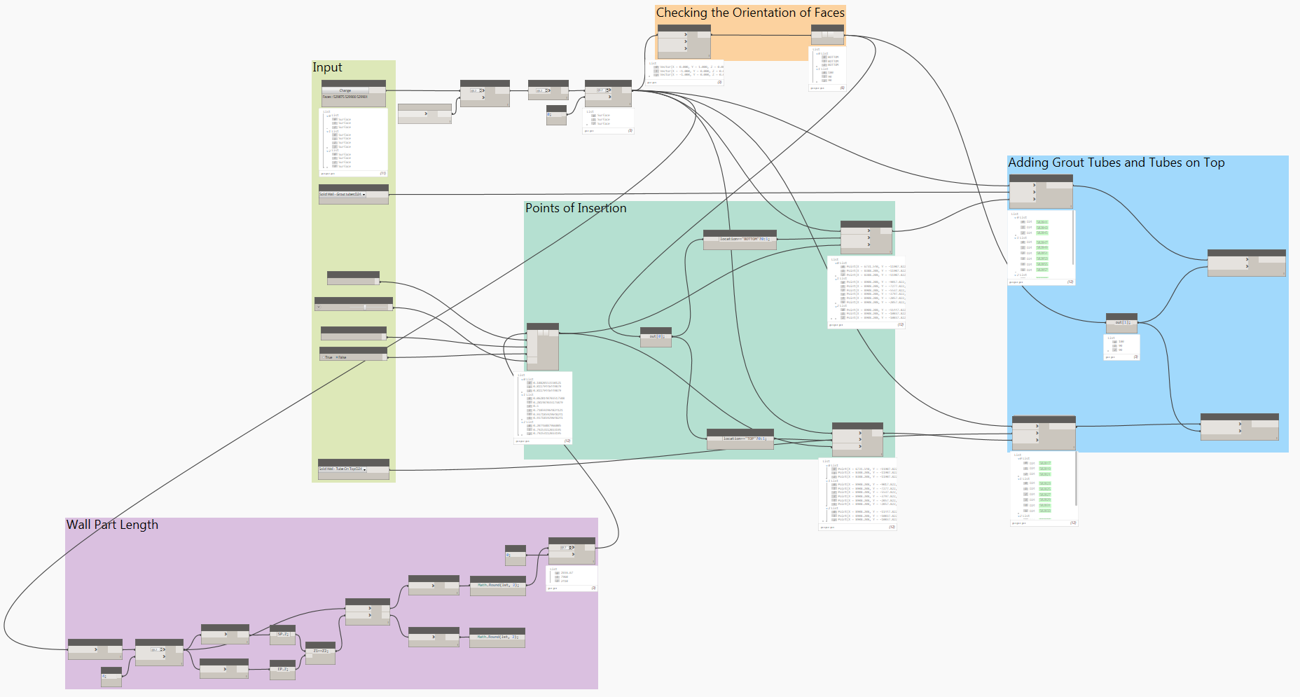
Now I have all data needed to calculate coordinates of insertion points for both grout tubes and tubes on top.

My next Python script helps me calculate where insertion points should be located taking into account all input parameters:


And finally I can add these tubes to my Revit model in the right location and with correct orientation. Here I used the Springs.FamilyInstance.ByFacePoints node available in the Spring Node package.
Adding Grout Tubes and Tubes on Top

All nodes:
This automated process of adding grout tubes saves tones of manual and tedious work and save a lot of time.
Watch video:
For more posts on structural precast in Revit, check out these past articles on BIM and Beam:
- Segmentation of Precast Walls in Revit
- Structural Precast for Revit – Configuration Settings
- Autodesk Structural Precast Extension for Revit Software Overview
- Announcing Autodesk Structural Precast Extension for Revit 2018, a notable step toward the future of automatically making structural things
- Precast Column with Corbels in Revit
@tomekf
The post Adding Grout Tubes to Precast Walls using Dynamo appeared first on BIM and Beam.
from my Autodesk source Bim & Beam: BIM and Beam at http://blogs.autodesk.com/bim-and-beam/2018/01/16/adding-grout-tubes-using-dynamo/
via IFTTT
Hi Shannon, Great to see such detail on a blog, I am trying to get a copy of the graph and grout tube family, are we to just create it from the pictures pasted here your help with this would be great
ReplyDeleteKevin