Monday, 26 December 2016

Attention to detail – Revit for rebar detailing

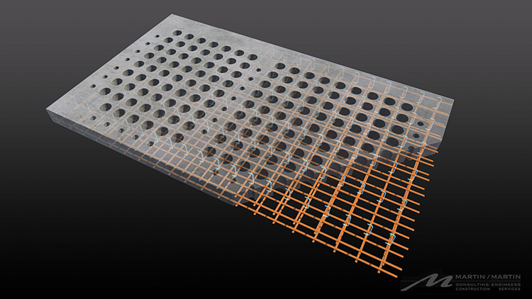
fab-slab-step-between-pan-joist-system-and-fab-slab-or-cheese-slab-realistic-model-view-reduced

Colorado-based Martin/Martin, Inc. is a consulting engineering firm providing civil and structural engineering and surveying services to clients throughout the United States and around the world. Within Martin/Martin, the Construction Engineering Services (M/M CES) group provides a variety of specialty engineering services to the firm’s contractor partners and projects, including the development of rebar shop and fabrication drawings. Both Martin/Martin and the M/M CES team use Autodesk Revit software for engineering design and documentation.

One of the firm’s most recent projects was the expansion of a semiconductor plant for Broadcom, located in Fort Collins, Colorado. During the past several years, the company invested approximately $1 billion in new construction on this 70-acre campus which included the addition and expansion of a new reinforced concrete manufacturing facility in 2014 and 2015. On both of these jobs, the extended project team—including Martin/Martin, M/M CES, and the general contractor JE Dunn Construction—used Building Information Modeling (BIM) processes and Revit software.

The major challenge on these projects was aggressive construction schedules. JE Dunn was engaged early in the projects and was actively involved in the design process to enhance constructability and keep the projects on track and within budget. “Close collaboration during the design phase of these projects resulted in higher quality buildings for the client,” says Shane Ewing, a principal at Martin/Martin and the manager of the M/M CES team. From previous experience with Martin/Martin and the M/M CES team, JE Dunn knew that one big opportunity for time savings during construction was concrete rebar detailing.

Revit for rebar detailing helps save time and money

“Rebar detailing typically begins several weeks after a contractor is awarded a project and is performed in isolation from the design team by a detailer working solely from 2D design drawings,” explains Ewing. “This situation forces a late start and often results in poor coordination with other trades, which further jeopardizes construction schedules.”

To help counter this situation, M/M CES used Revit to develop reinforcing steel fabrication drawings. “Instead of waiting until the construction documentation was completed, we started detailing during the design phase based on the structural designer’s Revit model,” says Grant Doherty, a BIM specialist at Martin/Martin. “By working closely with the design team, we could coordinate the rebar with the structure and other trades to improve constructability and quality.”

“Developing the steel reinforcement directly in the Revit structural design model, weeks before construction documents were available to anyone else, helped to provide significant schedule, quality, and cost benefits for the client—benefits that just couldn’t be matched using other detailing software.”

Shane Ewing, Principal, Manager of Construction Engineering Services, Martin/Martin

In addition, when the firm issued final construction documentation to JE Dunn, it also issued approved fabrication documentation. “Working with the design team and using a common Revit model, we began and completed our shop drawings earlier than a traditional ‘third party’ detailer would have,” says Ewing. For example, on a traditional project, rebar drawings are usually delivered five to eight weeks after the release of the construction documents. But on the first Broadcom building, the M/M CES team delivered an approved drilled pier and foundation rebar package in less than two weeks after the release of the construction documents. “With support from BIM processes and Revit for rebar detailing, we were able to save three to six weeks on this project,” says Ewing.

Model-based detailing and fabrication ready

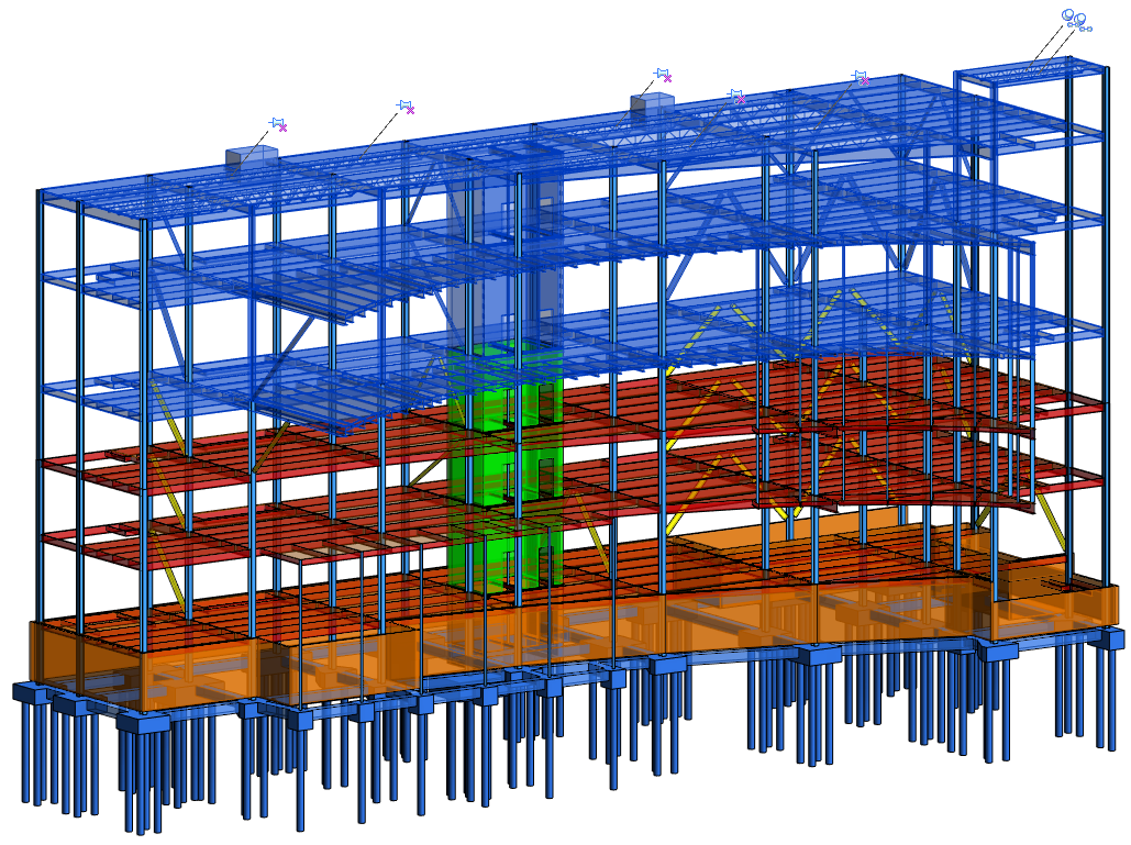
When working together on a project, the M/M CES team and Martin/Martin structural designers use the same Revit structural model, which often includes the architectural model as well as models from other building disciplines. On the Broadcom project, this enabled a level of project coordination what would not have been possible with traditional 2D detailing.

Beyond project coordination, using Revit for detailing also helped improve the overall quality of the firm’s rebar product. “Other detailing programs tend to ignore the experience and knowledge of the detailers by relying on software algorithms to add steel reinforcements,” says Doherty. “But more often than not, those algorithms don’t result in the best or most economical solution.” The Revit software and its 3D modeling environment helped the M/M CES team draw on their own detailing knowledge, as well as the experience of the Martin/Martin designers, to deliver the project’s fabrication package more efficiently and cost-effectively.

“Model-based detailing helps us work through complex design issues by using 3D views and live schedules to check the rebar,” says Doherty. “And because we work in tandem with the design team, we can see design changes as they happen and react more quickly. In fact, we can often release detailing revisions to the fabricator before the design team formally issues their changes.”

For its rebar detailing, M/M CES has created “fabrication ready” customized Revit rebar families. The rebar sizes, lengths, and bends in these families were all developed using industry standards and can be used by any North American fabricator.

Accelerate project schedules

With Revit, every drawing sheet, 2D and 3D view, and schedule is a direct presentation of the underlying model. The parametric engine at the heart of the Revit software enables the automatic synchronization of the model and all the associated drawings, views, and so on. “The automatic change management inherent in the Revit software helped us to quickly incorporate design changes,” says Doherty. “We could change the rebar in the Revit model, and that change automatically appeared in our fabrication drawings. There was no need for us to spend time on manual updating or quality control.”

Control costs

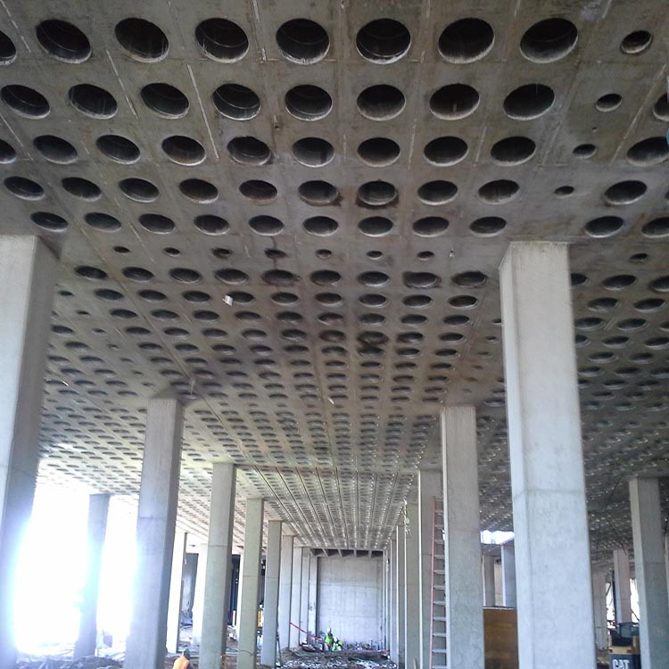
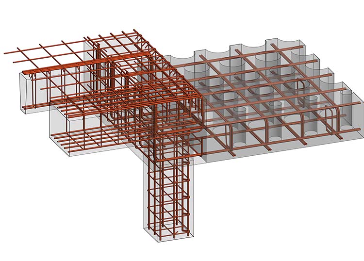
The Revit software and its 3D modeling environment helped Martin/Martin minimize project costs by enabling the M/M CES team to draw on their own detailing experience to more effectively layout the rebar and locate bar splices. For example, the first Broadcom project included a large concrete ‘waffle’ slab that needed a lot of reinforcement. “Working with the design team, the contractor, and the rebar placer, we were able to quickly try out different options in the Revit model and estimate tonnages to optimize the layout and splice locations,” says Doherty. As a result, the team was able to cut the number of bar splices in half, and reduce the tonnage by 8 tons and the number of bars handled by more than 2,000—helping Broadcom save an estimated 5 percent in material and labor costs.

Reduce field issues

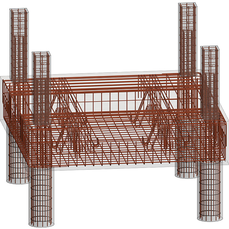
“Model-based project coordination combined with the completeness and quality of the fabrication drawings resulted in less field issues,” reports Ewing. In addition, the M/M CES team shared its Revit-based rebar model with the contractor and rebar installer to provide even more rebar information in a more accessible format. For example, the 3D rebar model enabled JE Dunn to coordinate the rebar with other trades and also use it as a starting point for its own concrete lift drawings.

The Revit rebar model was also used to easily create live section cuts through the rebar model and produce 3D perspective views of complex areas for visual clarification during construction. M/M CES even color-coded the rebar model to show the sequence of rebar installation. The ability to view the rebar model from any angle—either on a monitor in a trailer at the jobsite or even tablets in the field—helped the construction team visualize and better understand the rebar layout.

The results

“Using BIM processes and Revit software for rebar detailing helped us meet all of the project schedules,” says Doherty. “We delivered coordinated shop drawings earlier than would normally have been possible. And by relying on our own detailing experience, we delivered a higher-quality fabrication package that provided a better understanding of contract documents and helped minimize project costs.”

“Developing the steel reinforcement directly in the Revit structural design model, weeks before construction documents were available to anyone else, helped provide significant schedule, quality, and cost benefits for the client—benefits that just couldn’t be matched using other detailing software,” says Ewing.

Learn More

To learn more about Autodesk Revit’s features for structural engineers, including rebar detailing, visit Autodesk.com/products/revit-family. Or read these past blog posts on Revit’s features for rebar detailing:

The post Attention to detail – Revit for rebar detailing appeared first on BIM and Beam.


from my Autodesk source Bim & Beam: BIM and Beam at http://blogs.autodesk.com/bim-and-beam/2016/12/26/revit-for-rebar-detailing/
via IFTTT

Thursday, 22 December 2016

AU 2016 Gives a Glimpse into the Future for Structures

When reflecting on my experiences at Autodesk University last month, it reminded me of how technology dependent we’ve become at telling stories in both the digital and physical worlds.  It also illustrated to me that the boundaries between digital and physical modes of communication are becoming less distinct.   I heard stories from customers, technology partners and Autodeskers that were weaved into a broader digital tapestry of industry knowledge online. This illustrates to me that the era of connectivity is upon us whether we believe it or not. As discussed in my last blog, there are a number of trends that will change the face structural engineering and they all relate to changes in how we connect with each other and the things around us.   The future interplay between technology and people is an important topic of conversation for all of us to have. So why not start that conversation now with AU being fresh in our minds…

We saw nearly 10,000 AEC professionals attending AU this year and over 500 alone attending the MEP & Structural Fabricators Forum.  The theme was again focused on the Future of Making Things with a focus on high impact trends like robotics, generative design, machine learning and the cloud (to learn more about AU 2016, please check out this recent post from AECBytes).   I saw a common theme emerging at AU where AEC professionals are starting to focus on higher value services, while automating out the lower value services. This is happening out of necessity in order to remain competitive and anticipate the trends discussed above and a few other emergence technologies.  I would like to go into a few of these shifts in more depth:

First, I see the adoption of computational design accelerating within engineering firms already using BIM. Computational design is a visual method of programmatically creating, analyzing and choosing model-based designs.  Traditionally being viewed as having niche applications for architectural design exploration, we have seen greater adoption by more mainstream engineering teams for “human-centric automation.” What I mean by this is that computational design is enabling teams to automate out routine activities like internal QA/QC processes and data interoperability challenges. This not only improves profitability but also improves the quality of design deliverables.

At the same time, we see computational design adoption helping engineers focus on higher value services. For example, we see engineering firms connecting Dynamo to a range of products like Revit, Robot Structural Analysis and even Advance Steel to explore and refine the best design options for their clients. We also see it helping firms further differentiate their services. .  A great example of this was presented by Ben Osbourne, P.E. with Stanley D. Lindsey Associates. I encourage you all to watch this presentation because it is a great example of both computational design’s practical applications in traditional design and novel applications to differentiate extended services.(see Link).  Down the road, I expect engineers to offload simpler engineering tasks to computers supported by generative design and machine learning tools.  This will empower engineers to tackle more complex problems, especially those dependent upon stakeholders outside of the structure.

Second, I expect to see growing interest and adoption of Level of Development (LOD) based collaboration to automate the verification of BIM data at different stages of the project. The term LOD was created several years ago by the BIM Forum in the US. They created it tohelp create a common language for defining and exchanging model-based deliverables at the BIM object level.  As LOD-based model checking technologies like Invicara BIM Assure emerge in the industry, we see engineers and fabricators adopting them to automate QA/QC processes and improve the quality of design deliverables. In the future, we can predict that LOD-based industry standards will help fabricators and contractors accept validated design deliverables.  An example of how the structural steel industry is embracing LOD was presented at AU by Will Ikerd, PE, SE with Ikerd Consulting and memberof the BIM Forum (see link).

As LOD-based model checking automates the quality checking of design data, it will also empower engineers to focus on higher value problem solving.  Structural engineers will spend more time optimizing their designs not just for code compliance but for constructability factors such as material availability and relative “total installed” cost data. Forest Flager, PhD, with Stanford University’s CIFE program, presented the results of pilot projects that showed significant benefits by optimizing steel frame systems using structural steel availability and cost data (see link).  In the end, I see LOD being an important part of the structural design optimization process, both in early design or later when a fabricator is brought on board to deliver greater insight into the fabrication and installation costs. LOD will help establish clear expectations about what level of design information is delivered at different stages of the project.

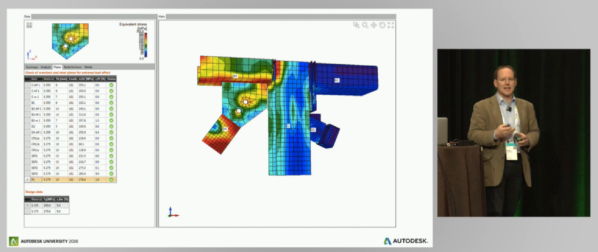
Third, I see engineers and detailers automating out routine code-based design decisions that also impact detailing and documentation.  We saw two examples of this presented at AU by Autodesk technology partners SOFiSTiK and Graitec. Both these companies provide design-driven detailing automation for concrete rebar all within a common BIM environment.  As engineers spend less time addressing routine calculation tasks that can be automated, they can focus on more advanced structural analysis methodologies and complex design solutions as presented by ARUP and Autodesk technology partner IDEA RS (see link).  Graham Aldwinckle with ARUP discussed the benefits of using advanced computational methods to optimize and analyze complex steel connections. What is novel about  IDEA RS Statica Steel is that it allows engineers to more quickly analyze the behavior of complex, non-typical steel connections using researched and validated computational methods. When such technology is connected to BIM, computational design and the cloud, I see engineers in the future able to run more “what if” scenarios of their overall steel frame design that also captures the complexities and impact of the steel connection design.  Using a more integrated and iterative process for structural design will free up engineers to spend more time defining what the real problem is and less time crunching through what the possible answers are.

Graham Aldwinckle (Director, ARUP London) presents an application of IDEARS Statica Steel to analyze existing steel connections as part of forensic engineering services.

Graham Aldwinckle (Director, ARUP London office) presents an application of IDEARS Statica Steel to analyze existing steel connections as part of forensic engineering services.

Fourth, with the access to greater cloud computing and the adoption of more standardized data models, engineers and detailers will be empowered to automate more of their structural detailing tasks for connection modeling and shop drawing production. As workforces become more global and integrated, we will see more automation in how models are exchanged between regional locations.  Doing so will free up detailers to focus on providing higher value services like BIM-centric trade coordination and competence in managing culturally and demographically diverse teams.  The development of these skill sets were discussed by steel construction leaders at AU in relation to managing globally dispersed steel detailing teams.  Joel Hicks, President of the National Institute of Detailing (NISD) and his peers discussed what NISD is doing to help prepare future steel detailers to work in a growingly more diverse and complex construction industry (see link).

Fifth (and last), the examples above all focus on how software automation is impacting the office. However, we are seeing machine automation on the factory floor as well.  Even though the steel fabrication industry has made great strides in becoming more efficient, there is still a great potential to leverage more modern manufacturing technologies like robotics and machine learning.   As seen at AU, steel manufacturer FICEP is preparing for this by investing inIFC based fabrication data exchanges. (see link).    This will enable greater use of robotics manufacturing on steel factory shop floor such as the assembly of shop parts and welding. As prefabrication of multiple systems including steel grow in the industry, the use of robotics will demand even greater use of BIM

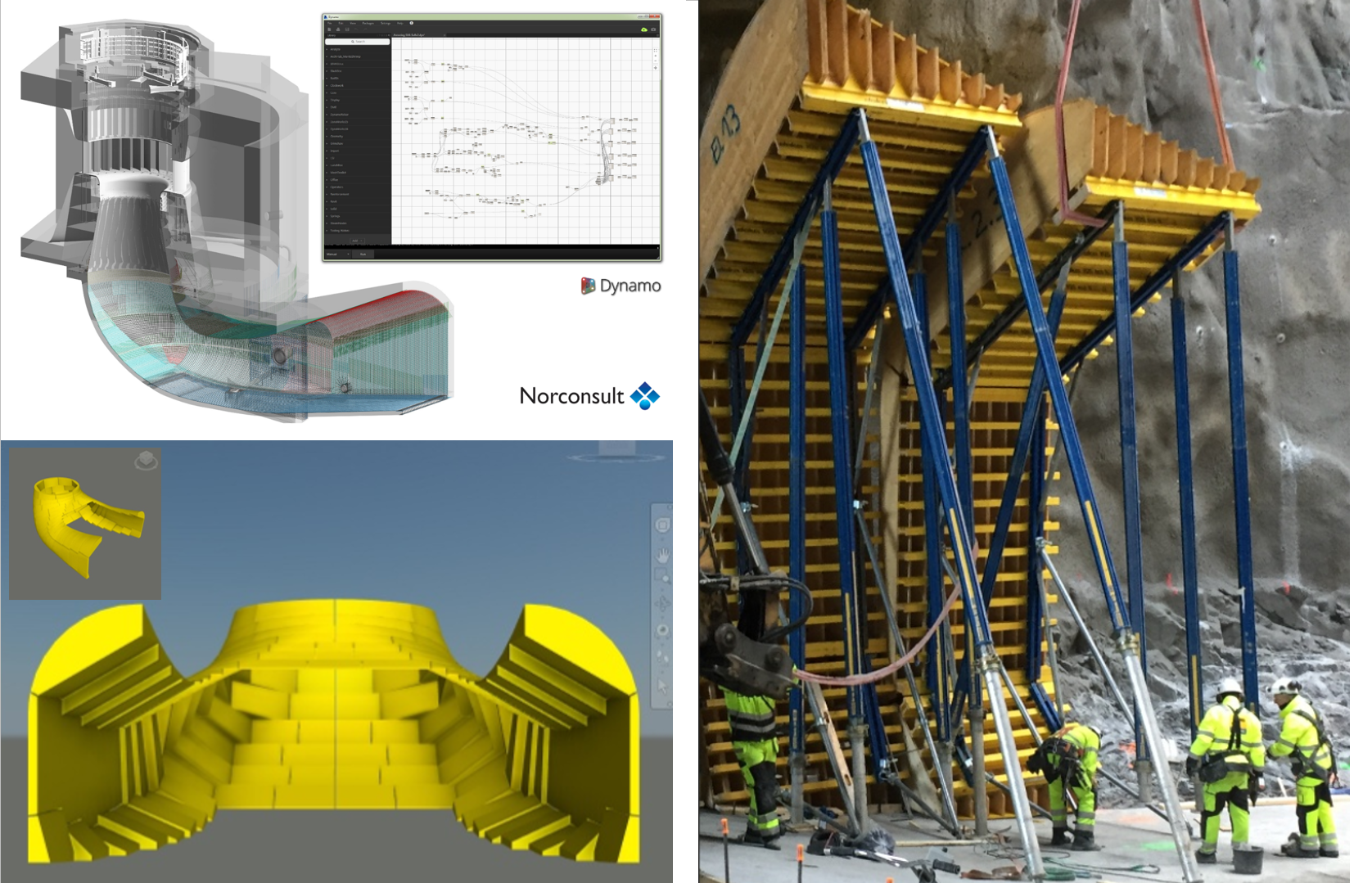
We are seeing this trend of prefabrication happening not just in the factory but also in the field. My favorite presentation at AU this year was a presentation by Marius Jablonskis with Norconsult. Marius presented a compelling story about the design and construction of Vamma 12, a large hydro project in Norway (see link). The Vamma project is unique in that the design deliverables are contractually 100% model-based and do not use paper. By eliminating the need for drawing creation, Norconsult could focus more time on optimizing the design to help the construction teams fabricate and build a better product. This shift away from paper was also seen by the contractors. The formwork supplier fabricated their formwork using Norconsult’s 3D model as a start point, not using drawings. The contractor also used Norconsult’s concrete model to establish survey points that guided the path of the rock excavation machine.  This application of subtractive manufacturing principles on the construction site is a great example of how engineers and contractors deliver greater value to their clients in the future.

vamma_for_bb_2016

For their paperless hydro project in Norway called Vammaa 12, Norconsult is using Revit to model all the reinforced concrete in 3D. This model is used by the formwork supplier Doka to more efficiently fabricate the complex formwork. (Images: Courtesy of Norconsult)

I do believe these examples seen at Autodesk University 2016 paint yet another picture  of how we will make structural things in the future….and the role of people and technology in doing it.  Engineers will need to solve more complex engineering problems and fabricators will have to adapt to more complex collaborative environments, all being driven by trends like prefabrication and globalization of work.  They will also need to become better storytellers. The use of more compelling visualization and “storytelling” technology will position engineers and fabricators to be better communicators and leaders on their projects.   To differentiate their businesses and ultimately survive, our peers in structural engineering and fabrication must shift their efforts to high-value services and automate the low-value services.

So do you agree? Are you seeing this trend happening around you?  I would love to hear your feedback about this topic.

The post AU 2016 Gives a Glimpse into the Future for Structures appeared first on BIM and Beam.


from my Autodesk source Bim & Beam: BIM and Beam at http://blogs.autodesk.com/bim-and-beam/2016/12/22/au-20176-gives-glimpse-future-structures/
via IFTTT

Tuesday, 20 December 2016

Tips and Tricks for using Autodesk Advance Steel from AU2016 (Part 1)

When you think Autodesk University, you probably think about learning the latest trends and technologies but also tips & tricks on your favorite products. And that’s just what you’ll find! This year at AU we had a number of classes dedicated to helping users build models more efficiently in Advance Steel. For this post, I’m going to summarize some of the tips and tricks for using Autodesk Advance Steel that I described in my class during the Autodesk University MEP & Structural Fabricators Forum 2016, and help you discover little-known features in the modeling environment.

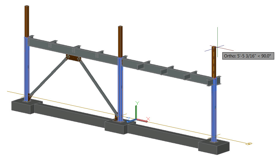
1. Stretching multiple columns

You can stretch multiple columns without doing it for them all individually.

Select the columns to be stretched, then hold down Shift and select grips so that they are highlighted. Release Shift and select a grip as the base grip by clicking the grip and move it.

Advance Steel 2016 Tips and Tricks

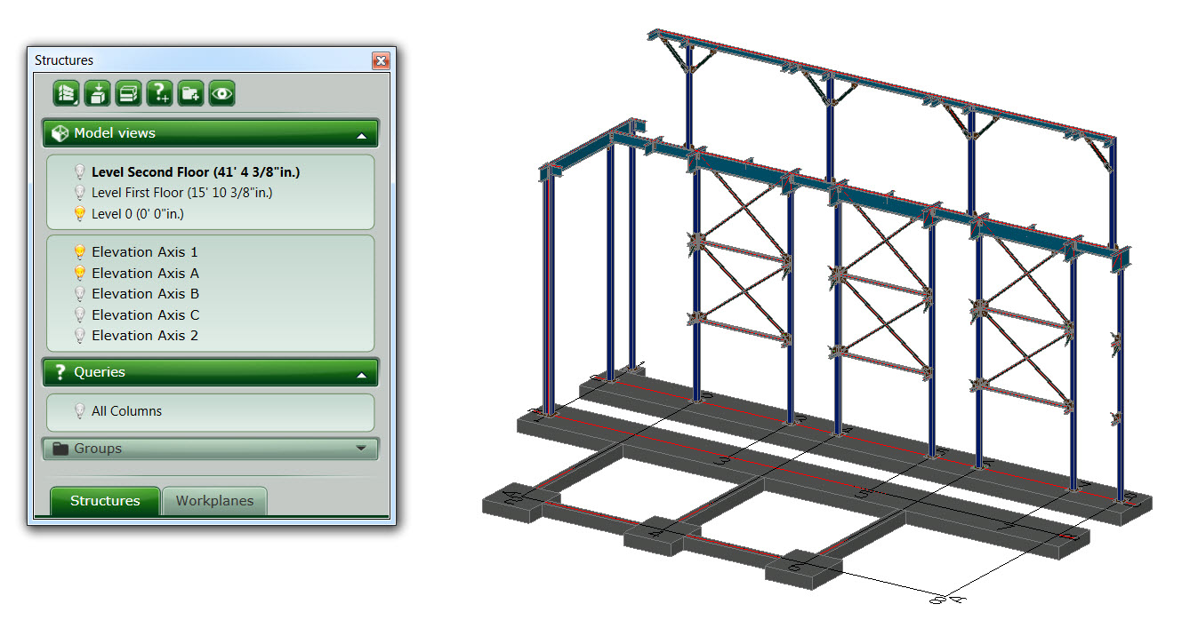
2. Displaying several model views

You can select more than one light bulb icon in front of the model views in the Project Explorer to get several model views being displayed at the same time, which helps quickly visualize parts of your 3D model.

Advance Steel Tips and Tricks

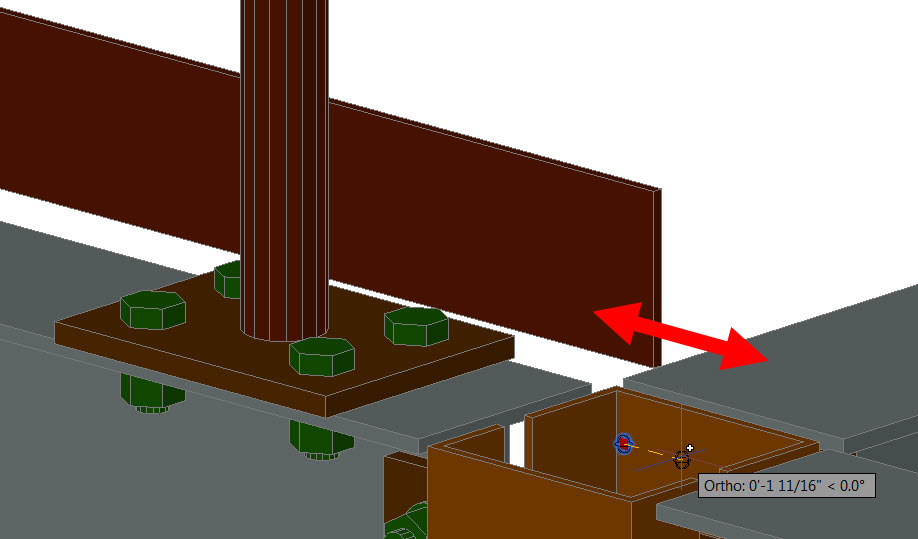
3. Transferring properties from a connection to other ones

A very handy tool is the “Transfer properties” command available in the “Extended Modeling”, which helps you transfer properties from an automatic connections to other similar connection(s).

Advance Steel Tips and Tricks transferring-properties-from-a-connection-to-other-ones

4. Extending a railing with its grip points

You can extend or shorten a railing by moving the ball grip at one of the railing ends, which makes it really easy to modify its length.

Advance Steel tips and tricks-extending-a-railing-with-its-grip-points

5. Locating various objects based on specific properties

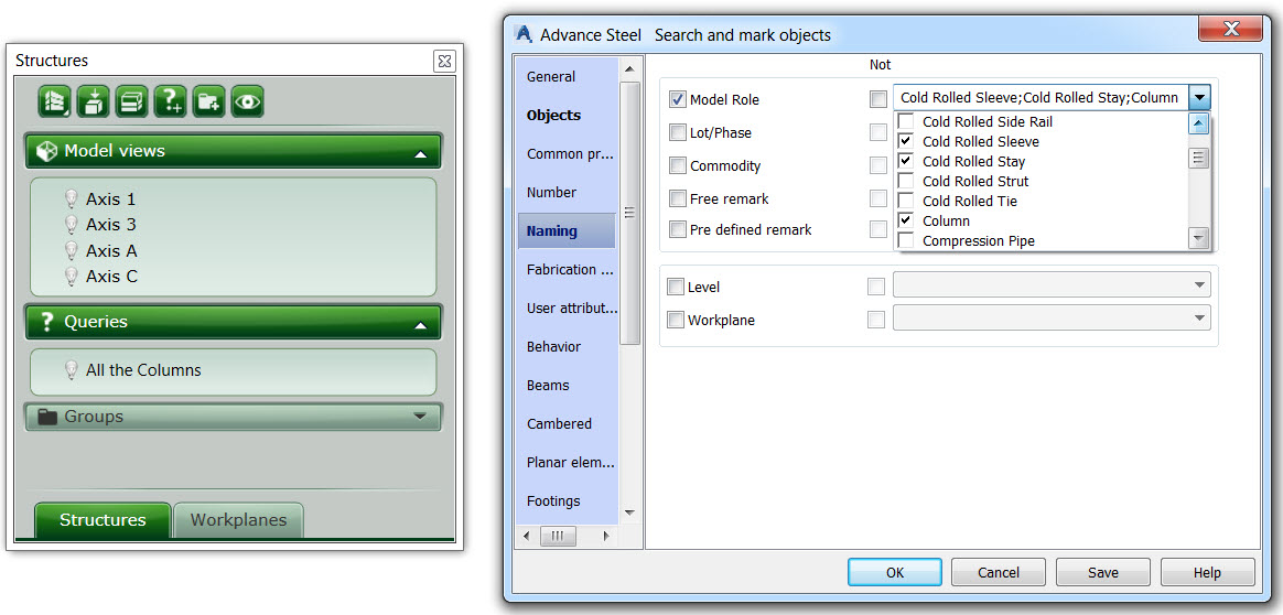
When working on a structure you might need to locate various objects based on specific properties. For example, you might want to select all the objects which have specific model roles. Search criteria can then be saved and reused as a query at any time from the project explorer!

Advance Steel Tips and Tricks-locating-various-objects-based-on-specific-properties

If you’re interested in watching the full class on-demand, visit Autodesk University online here. And check back in a few weeks for Part II of this blog post.

For more tips on using Advance Steel, check out these previous blog posts:


The post Tips and Tricks for using Autodesk Advance Steel from AU2016 (Part 1) appeared first on BIM and Beam.


from my Autodesk source Bim & Beam: BIM and Beam at http://blogs.autodesk.com/bim-and-beam/2016/12/20/tips-and-tricks-for-using-autodesk-advance-steel-from-au2016-part-1/
via IFTTT

Monday, 19 December 2016

Rebar Shape Images in Revit

Scheduling is the operation of listing the location, mark, type and size, number off, length and bending details of each bar or sheet of fabric. When dealing with bars the completed lists are called “bar schedules”. The bars should be grouped together
for each structural unit, e.g. beam, column, etc. In a building, the bars should be listed floor by floor.

The form of bar and fabric schedule and the shapes of bar used should be in accordance with local standards. It is also preferable that bars should be listed in the schedule in numerical order.

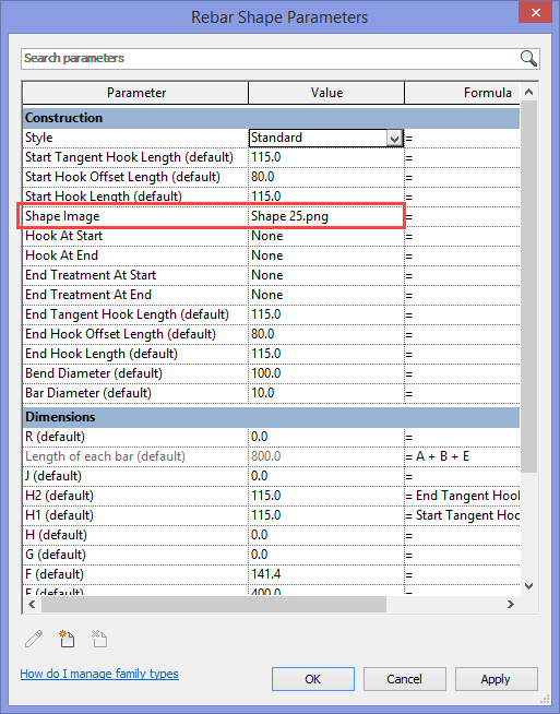
Since a few versions already, Revit allows us to add an image to a family instance or type with the “Image” or “Type Image” parameter. For Rebar families there is the “Shape Image” parameter, which makes it possible to create well formatted rebar bending schedules, including the rebar shape image.

family-type-parameters1

images

Out-of-the-box, Revit offers Rebar Shapes according to the local requirements and codes for a lot of countries around the world. These Rebar Shapes don’t contain these Shape Images, to make it possible for you as a user to customize this.

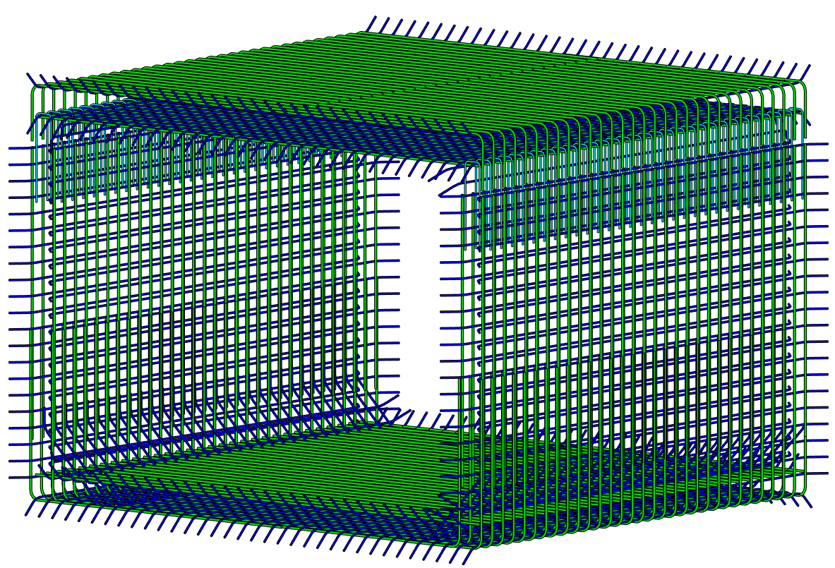
3d-rebar

For rebar schedule representations during demos of “Rebar with Revit”, my colleague Dieter edited the default rebar shape families and added the shape code images according to BS8666 : 2005, to the Shape Image parameter.

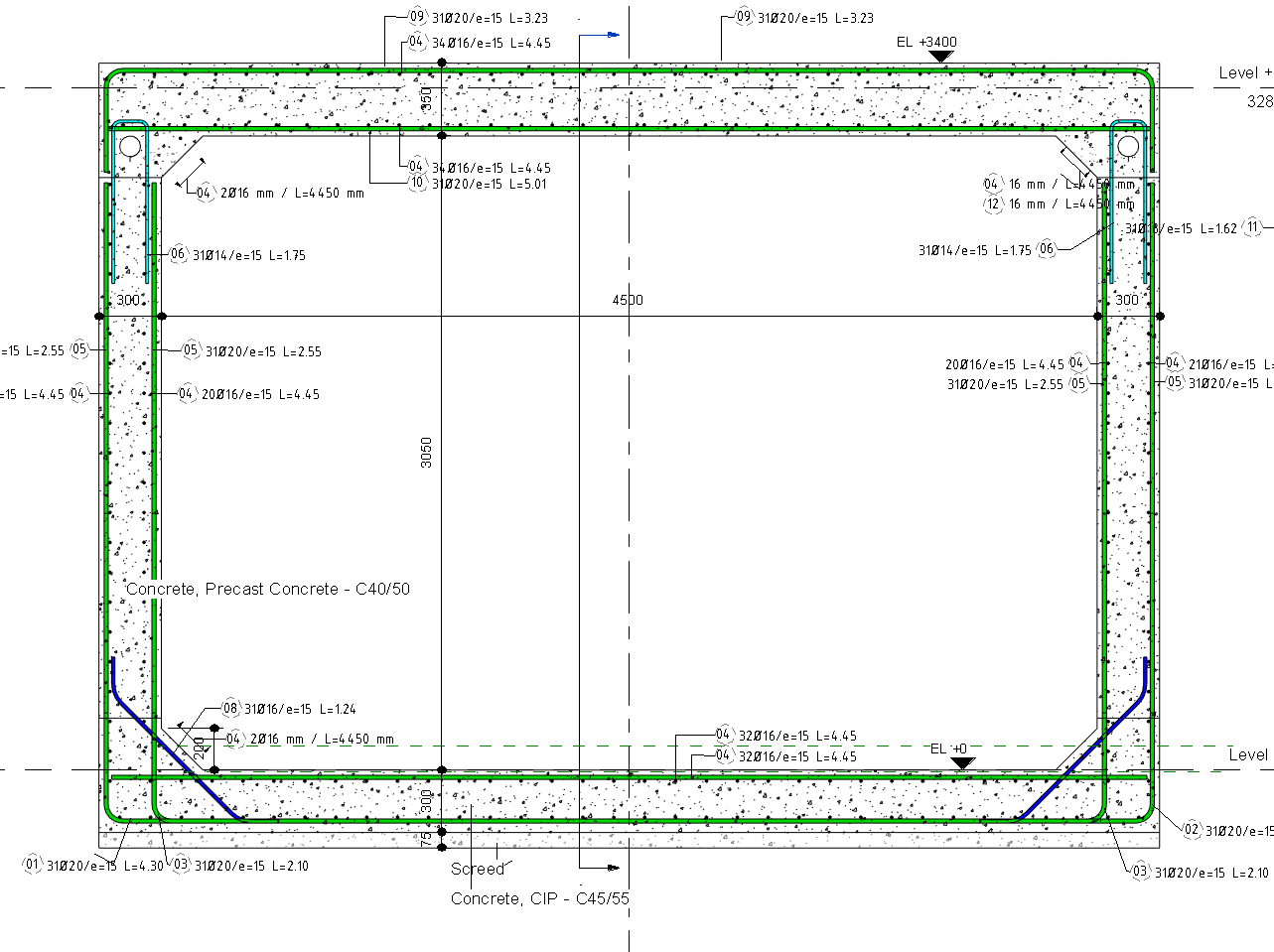
rebar-section

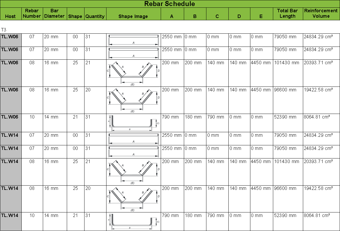
This resulted in these nice formatted bending schedules for a simple reinforced concrete tunnel.

rebar-schedule

The content that is used for this small model can be downloaded from here.

The post Rebar Shape Images in Revit appeared first on BIM and Beam.


from my Autodesk source Bim & Beam: BIM and Beam at http://blogs.autodesk.com/bim-and-beam/2016/12/19/rebar-shape-images-in-revit/
via IFTTT

Sunday, 11 December 2016

Needed: Beta testers for Steel Connections for Revit

Steel connections for Revit beta

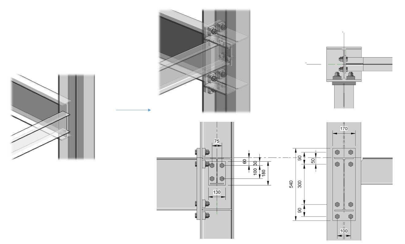
With Revit 2017 Autodesk delivered an extension allowing users to create steel connections in Revit. This functionality gives engineers the ability to model their steel designs to a higher level of detail. For an upcoming release, we are bringing even more capabilities and functionalities to the steel environment, including:

  • Free-modeling miscellaneous steel elements like bolts and plates
  • Ability to create cuttings and drillings on steel elements
  • Continuous interoperability between Advance Steel and Revit
  • 133 types of standard steel connections as parametrized objects
  • Access to individual parts of connection
  • Ability to create dimensions, tags and schedules for individual parts of a connection

Be a beta tester

The Revit structure team is looking for users to help us beta test our new release and provide feedback to make the software better. If you’re interested in joining our beta testing team, please reach out to Autodesk senior user experience designer, Andreea Dumbrava (andreea.dumbrava@autodesk.com), and she’ll add you to the private forum for testers.

Learn more about Steel Connections for Revit

The current extension is available for Revit subscribers and can be downloaded and installed from the Autodesk Desktop App or through your Autodesk Account. Watch out this video if you want to know more about how to install it on your computer.

Learn more about Steel Connections for Revit and Autodesk’s plans for the structural features in Revit:

The post Needed: Beta testers for Steel Connections for Revit appeared first on BIM and Beam.


from my Autodesk source Bim & Beam: BIM and Beam at http://blogs.autodesk.com/bim-and-beam/2016/12/12/needed-beta-testers-for-steel-connections-for-revit/
via IFTTT

Thursday, 8 December 2016

WHAT ARE THE PROPERTIES OF AIR ENTRAINED CONCRETE?

AIR ENTRAINED CONCRETE A major advance in concrete technology in recent years is the introduction of tiny disconnected air bubbles into concrete called air entrainment. Air entrained concrete results from using either an air-entraining cement or an air-entraining admixture during mixing. Adding entrained air to concrete provides important benefits in both plastic and hardened concrete, […]

The post WHAT ARE THE PROPERTIES OF AIR ENTRAINED CONCRETE? appeared first on CivilBlog.Org.


from CivilBlog.Org http://civilblog.org/2016/12/09/properties-air-entrained-concrete/
via Our favorite Civil Engineering Blog

Wednesday, 7 December 2016

5 great features in Structural Analysis for Revit

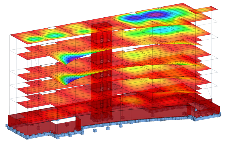
Structural Analysis for Revit provides cloud-based structural analysis to structural engineers as a part of the BIM process. With Structural Analysis for Revit, engineers and designers can extend design models from Revit to the cloud for structural analysis. Results can then be visualized and explored within Revit and disruptions to a designer or engineer’s workflow are minimized by performing analysis in the cloud as design continues.

Structural Analysis

Here are 5 things you might not know about this service.

1. You can analyze a whole analytical model or a part of it.

For a selected part of a structure, supports are created automatically in places where the model is cut off from the project.


structural-analysis-selected-part-02

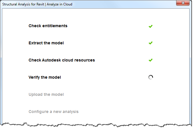
2. Before you define parameters of your analysis the service extracts the analytical model from the Revit project.

It checks the cloud resources and then it checks if the analytical model has already been uploaded to the cloud. Finally it verifies and uploads the model to the cloud.

structural-analysis-verify-the-modelVerification of the model before it is uploaded checks if it is correct from the viewpoint of structural analysis. This verification ensures that the model being analyzed is correct and the analysis results are reliable. It also prevents uploading models with errors to the website.
 3. There are two types of analysis you can perform on your structural models:

  • Static analysis
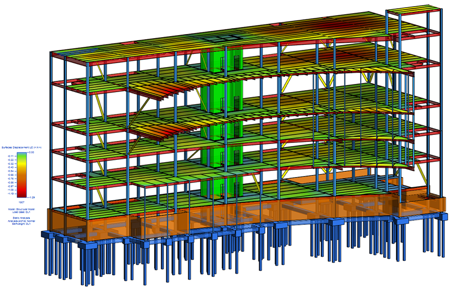
  • Gravity analysis: It is a simplified analysis. By deducing the flow paths of loads it lets you determine how vertical loads are transmitted from the top to the foundation of the model.

structural-analysis-types-of-analysis

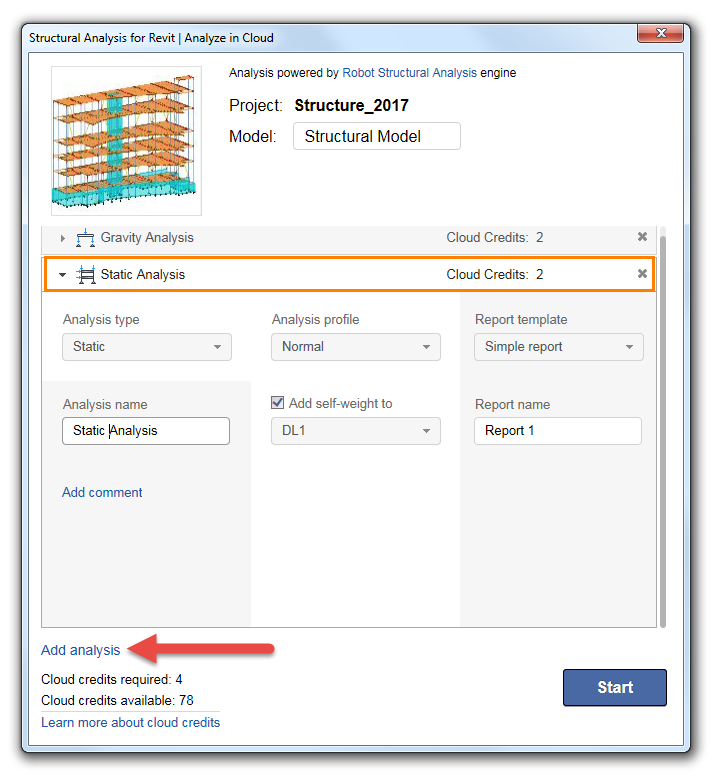
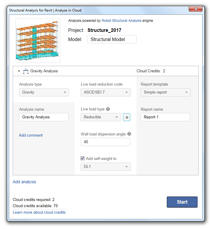
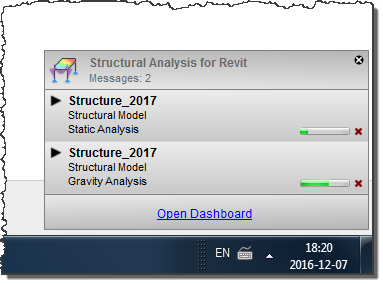
4. You can run a few parallel analyses helping to increase your productivity.

Traditionally conducting structural analysis is time intensive requiring extensive computing power, however, with Structural Analysis for Revit, a designer or engineer can continue their design in Revit while static or gravity analysis is performed in the cloud. As analysis is conducted, designers and engineers can work on structural documentation or run another parallel analysis with a different set of parameters of the analysis.

structural-analysis-parallel-analyses-01

structural-analysis-parallel-analyses-02

You can define a new analysis in the Analyze in Cloud dialog …

structural-analysis-add-analysis-01

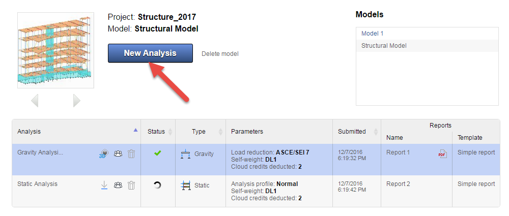
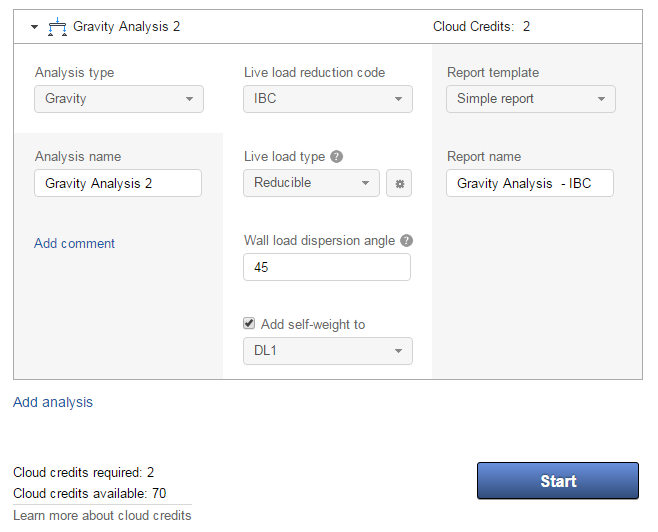
…or when your model is already uploaded you can do it from within the Structural Analysis website.
structural-analysis-add-analysis-02

structural-analysis-add-analysis-03

5. When analysis is complete you can explore the results of analysis in the various ways.

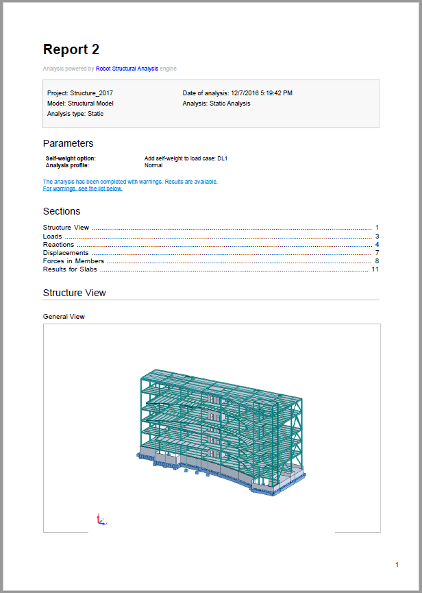
  • Results are available in the form of predefined analysis reports on the Structural Analysis website. You can view them in the HTML or PDF format. You can also download and save them locally.

structural-analysis-results-01
structural-analysis-results-02

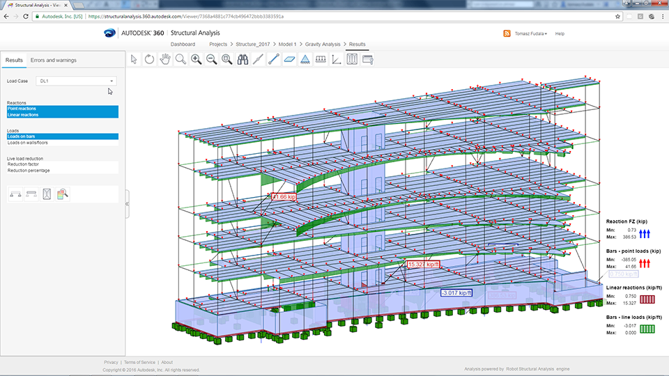
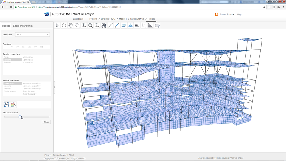
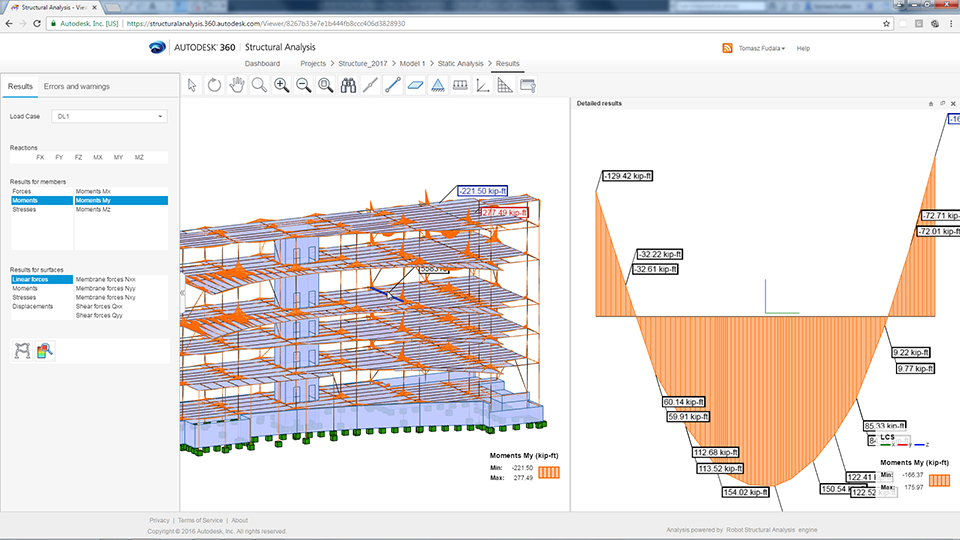
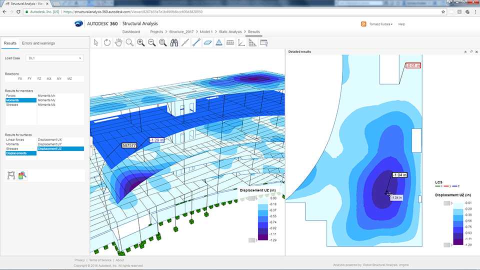
  • You can use the 3D Structure Viewer in your browser to explore result types for static and gravity analysis. You can also display additional result types and detailed results for an element. If errors or warnings are reported during analysis, you can identify the elements causing them in the Viewer.

structural-analysis-results-03s

structural-analysis-results-04s

You can simultaneously display several result types in the view and in the detailed view.

structural-analysis-results-06s

structural-analysis-results-05s

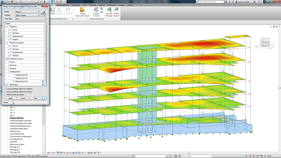
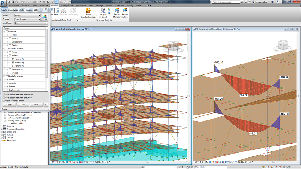
  • Analysis results can be easily stored and explored in the Revit environment too. Structural Results Manager and Results Exploration tools enable you to explore and document results so you can gain knowledge on a structure’s behavior, and have insight in consolidated and detailed results, in order to make appropriate design decisions as well as properly document them.structural-analysis-tools

structural-analysis-results-07s

structural-analysis-results-08sResults Manager dialog box shows the list of available results packages, as well as their status and location. The results of the analysis you performed can be stored in several ways:
  • Locally: in the Revit project.
  • Remotely: on the cloud server. In this case, the size of the package is also indicated.
  • In project and in the cloud.

structural-analysis-results-manager

Performing cloud based analysis from within Revit helps to streamline the design process and provide analytical results early and often to inform intent.

structural-analysis-results-10

You can download Structural Analysis for Revit from the Autodesk Apps Store.

The post 5 great features in Structural Analysis for Revit appeared first on BIM and Beam.


from my Autodesk source Bim & Beam: BIM and Beam at http://blogs.autodesk.com/bim-and-beam/2016/12/07/5-great-features-in-structural-analysis-for-revit/
via IFTTT